Nissan Silvia. Manual - part 242
SEM042F
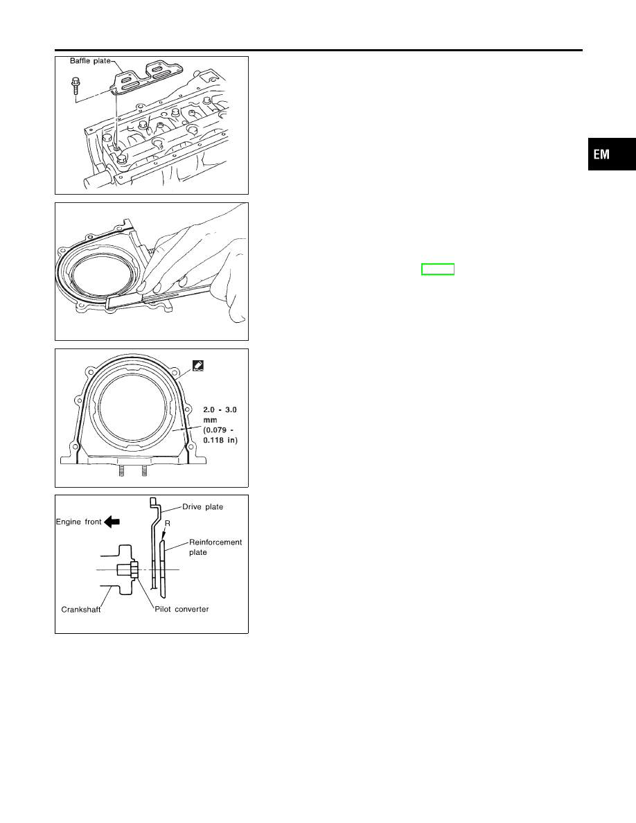
7.
Install baffle plate.
SEM218D
8.
Install rear oil seal retainer.
a.
Before installing rear oil seal retainer, remove old liquid gasket
from mating surface.
I
Also remove old liquid gasket from mating surface of cylinder
block.
b.
Install rear oil seal. Refer to EM-35, “REAR OIL SEAL”.
SEM219DA
c.
Apply a continuous bead of liquid gasket to mating surface of
rear oil seal retainer.
I
Use Genuine Liquid Gasket or equivalent.
I
Apply around inner side of bolt holes.
SEM624G
9.
Install rear plate.
10. Install flywheel or drive plate (A/T models).
I
Install reinforcement plate (A/T models) directing the
rounded edge side to drive plate.
GI
MA
LC
EC
FE
CL
MT
AT
PD
AX
SU
BR
ST
RS
BT
HA
SC
EL
IDX
CYLINDER BLOCK
Assembly (Cont’d)
EM-81