Nissan Almera Tino V10. Manual - part 697
MBIB0906E
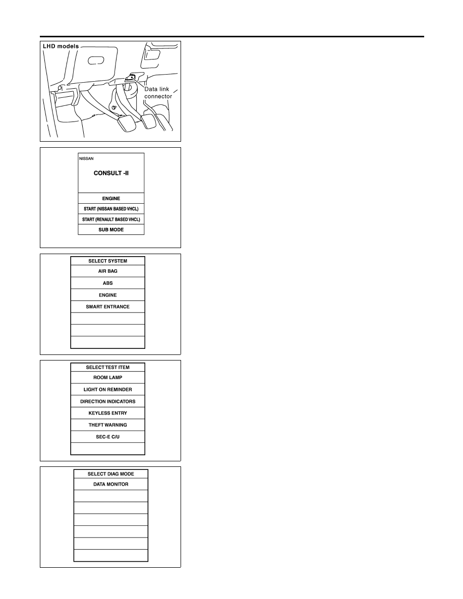
CONSULT-II Inspection Procedure
=NLEL0681
“ROOM LAMP”
1.
Turn ignition switch “OFF”.
2.
Connect “CONSULT-II” to the data link connector.
MBIB0233E
3.
Turn ignition switch “ON”.
4.
Touch “START (NISSAN BASED VHCL)”.
YEL322E
5.
Touch “SMART ENTRANCE”.
YEL324E
6.
Touch “ROOM LAMP”.
SEL788W
7.
Select diagnosis mode.
“DATA MONITOR” are available for “ROOM LAMP”.
INTERIOR ROOM LAMP
CONSULT-II Inspection Procedure
EL-84