содержание .. 852 853 854 855 ..
Nissan Murano Z51. Manual - part 854
BLOWER MOTOR
HAC-71
< DTC/CIRCUIT DIAGNOSIS >
[WITHOUT 7 INCH DISPLAY]
C
D
E
F
G
H
J
K
L
M
A
B
HAC
N
O
P
NO
>> Repair harness or connector.
6.
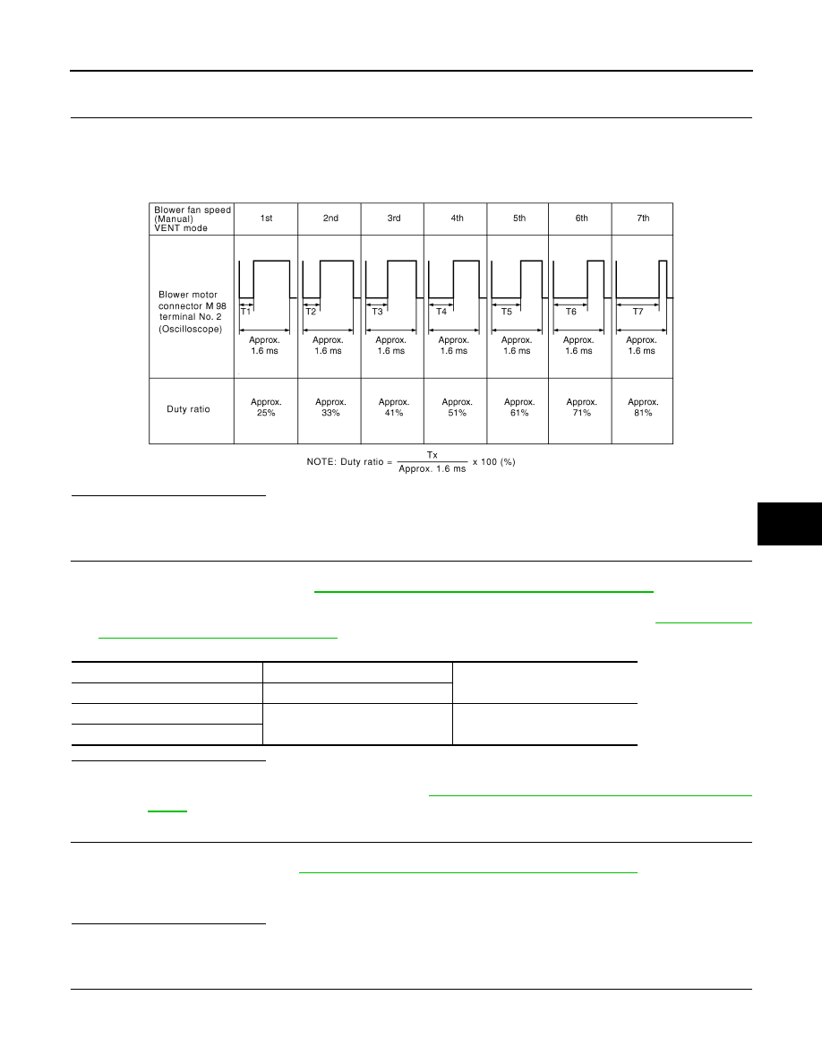
CHECK A/C AUTO AMP. OUTPUT SIGNAL
1.
Reconnect blower motor connector and A/C auto amp. connector.
2.
Turn ignition switch ON.
3.
Set MODE switch to the VENT position.
4.
Check the output waveform between blower motor harness connector and ground using an oscilloscope,
while varying the fan speed from 1 to 7.
Is the inspection result normal?
YES
>> Replace the blower motor.
NO
>> Replace the A/C auto amp.
7.
CHECK POWER VOLTAGE OF BLOWER RELAY
1.
Turn the ignition switch OFF.
2.
Remove the blower relay. Refer to
PG-113, "Fuse, Connector and Terminal Arrangement"
3.
Turn the ignition switch ON.
4.
Check the voltage between blower relay fuse block side terminal and ground. Refer to
Connector and Terminal Arrangement"
for relay terminal assignment.
Is the inspection result normal?
YES
>> GO TO 8.
NO
>> Inspection the power supply circuit. Refer to
PG-67, "Wiring Diagram - IGNITION POWER SUP-
8.
CHECK BLOWER RELAY
1.
Turn the ignition switch OFF.
2.
Install the blower relay. Refer to
PG-113, "Fuse, Connector and Terminal Arrangement"
3.
Turn the ignition switch ON.
4.
Check the operating sound of blower relay.
Is the inspection result normal?
YES
>> GO TO 9.
NO
>> Replace the blower relay.
9.
CHECK FUSE
Check 15A fuses (Nos. 21 and 22).
NOTE:
JPIIA0616GB
(+)
(
−
)
Voltage
Blower relay
—
1
Ground
Battery voltage
3