Nissan Qashqai J11. Manual - part 855


  Index      Nissan     Nissan Qashqai J11 - Service and Repair Manual


Search            


Content   ..  853  854  855  856   ..


Nissan Qashqai J11. Manual - part 855


FSU-10

< REMOVAL AND INSTALLATION >

FRONT COIL SPRING AND STRUT

Removal and Installation

INFOID:0000000010297071

REMOVAL

1.

Remove tires from vehicle.

2.

Remove wheel hub lock nut.
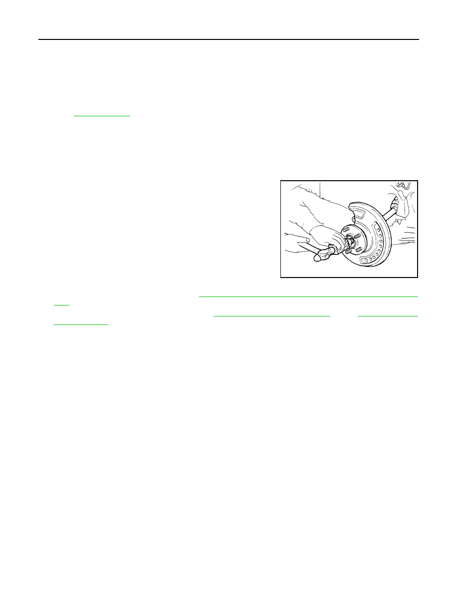
3.

Tap wheel hub lock nut with a piece of wood to disengage wheel
hub and bearing from drive shaft.
NOTE:
Use a suitable puller if wheel hub and bearing and drive shaft
cannot be separated even after performing the above proce-
dure.

4.

Remove brake rotor and caliper. Refer to 

BR-37, "BRAKE CALIPER ASSEMBLY : Removal and Installa-

tion"

.

5.

Remove the brake hose lock plate from strut.  

BR-19, "FRONT : Exploded View"

 (LHD), 

BR-63, "FRONT :

Exploded View"

 (RHD).

6.

Remove the bolt and separate the front wheel sensor from the steering knuckle. Separate the harness
from the brackets and position aside.

CAUTION:

• Failure to separate the front wheel sensor from the steering knuckle may result in damage to the

front wheel sensor.

• Pull out the front wheel sensor, being careful to turn it as little as possible. Do not pull on wheel

sensor harness.

7.

Remove the nut and separate the stabilizer connecting rod from the strut bracket.

8.

Separate axle transverse link and steering knuckle.

9.

Remove front strut lower bolt.

1.

Strut mounting insulator

2.

Strut mounting bearing

3.

Bound bumper

4.

Coil spring

5.

Lower rubber seat

6.

Strut 

7.

Steering knuckle

8.

Stabilizer connecting rod

9.

Stabilizer clamp

10. Stabilizer bushing

11. Stabilizer bar

12. Front suspension member

13. Rebound stopper rubber

14. Front suspension member stay

15. Transverse link

16. Rear suspension member stay

17. Front suspension member insulator

Refer to 

GI-4, "Components"

 for symbols in the figure.

JPDIG0070ZZ

FRONT COIL SPRING AND STRUT

FSU-11

< REMOVAL AND INSTALLATION >

C

D

F

G

H

I

J

K

L

M

A

B

FSU

N

O

P

10. Open the slot using a chisel (NI-4038) (A). Separate the steering

knuckle (1) from the front coil spring and strut.

CAUTION:

• Never drop steering knuckle.

11. Separate strut lower.
12. Remove knuckle assembly (knuckle and wheel hub).

13. Remove strut upper bolts.

14. Remove front strut from the vehicle.

INSTALLATION

CAUTION:

• Never reuse the wheel hub lock nut.
• Never reuse the cotter pin.
• Never reuse steering knuckle upper bolt.
• Never reuse steering knuckle lower nut.
Note the following, and install in the reverse order of removal.
• Perform final tightening of bolts and nuts, under unladen conditions with tires on level ground.

Disassembly and Assembly

INFOID:0000000010297072

DISASSEMBLY

CAUTION:

Never damage strut assembly piston rod when removing components from strut assembly.
1.

Install strut attachment (A) (SST: ST35652000) to strut assem-
bly and secure it in a vise.

CAUTION:

When installing the strut attachment to strut assembly,
wrap a shop cloth around strut to protect from damage.

ALDIA0492ZZ

JPEIA0006ZZ

FSU-12

< REMOVAL AND INSTALLATION >

FRONT COIL SPRING AND STRUT

2.

Using a spring compressor (A) (commercial service tool), com-
press coil spring between strut mounting bearing and lower rub-
ber seat (on strut assembly) until coil spring with a spring
compressor is free.

CAUTION:

Be sure a spring compressor is securely attached to coil
spring. Compress coil spring.

3.

Make sure coil spring with a spring compressor between strut
mounting bearing and lower rubber seat (strut assembly) is free.
And then remove piston rod lock nut while securing the piston
rod tip so that piston rod does not turn.

4.

Remove strut mounting insulator and strut mounting bearing,
and bound bumper from strut.

5.

After remove coil spring with a spring compressor, and then gradually release a spring compressor.

CAUTION:

Loosen while making sure coil spring attachment position does not move.

6.

Remove lower rubber seat from strut.

7.

Remove the strut attachment (SST: ST35652000) from strut.

ASSEMBLY

1.

Install strut attachment (SST: ST35652000) to strut and secure it in a vise.

CAUTION:

When installing the strut attachment to strut assembly, wrap a shop cloth around strut to protect
from damage.

2.

Install lower rubber seat.

3.

Install bound bumper.

4.

Compress coil spring using a spring compressor (commercial service tool), and install it onto strut assem-
bly.

CAUTION:

• Face tube side of coil spring (1) downward. Align the

lower end (A) to lower rubber seat (2).

• Be sure a spring compress is securely attached to coil

spring. Compress coil spring.

5.

Install strut mounting bearing and strut mounting insulator to strut.

6.

Secure piston rod tip so that piston rod does not turn, then tighten piston rod lock nut with specified
torque.

CAUTION:

Never reuse piston rod lock nut.

7.

Gradually release a spring compressor, and remove coil spring.

CAUTION:

Loosen while making sure coil spring attachment position does not move.

8.

Remove the strut attachment from strut assembly.

Inspection

INFOID:0000000010297073

INSPECTION AFTER REMOVAL

Strut
Check the following items, and replace the parts if necessary.
• Strut for deformation, cracks or damage
• Piston rod for damage, uneven wear or distortion

JPEIA0007ZZ

Maximum Gap (A)

: 5mm (0.2 in)

JPEIA0027ZZ

FRONT COIL SPRING AND STRUT

FSU-13

< REMOVAL AND INSTALLATION >

C

D

F

G

H

I

J

K

L

M

A

B

FSU

N

O

P

• Oil leakage
Strut Mounting Insulator and Rubber Parts InspectionCheck strut mounting insulator for cracks and rubber
parts for wear. Replace it if necessary.
Coil SpringCheck coil spring for cracks, wear or damage. Replace it if necessary.

INSPECTION AFTER INSTALLATION

1.

Check wheel alignment. Refer to 

FSU-7, "Wheel Alignment Inspection"

.

2.

Adjust neutral position of steering angle sensor. Refer to 

BRC-64, "Work Procedure"

.

Disposal

INFOID:0000000010425116

1.

Set front coil spring and strut horizontally to the ground with the piston rod fully extracted.

2.

Drill 2 – 3 mm (0.08 – 0.12 in) hole at the position (

) from top

as shown in the figure to release gas gradually.

CAUTION:

• Wear eye protection (safety glasses).
• Wear gloves.
• Be careful with metal chips or oil blown out by the com-

pressed gas.

NOTE:
• Drill vertically in this direction (

).

• Directly to the outer tube avoiding brackets.
• The gas is clear, colorless, odorless, and harmless.

3.

Position the drilled hole downward and drain oil by moving the piston rod several times.

CAUTION:

Dispose of drained oil according to the law and local regulations.

A:

20 – 30 mm (0.79 – 1.18 in)

ALEIA0200ZZ


Content   ..  853  854  855  856   ..