Nissan Qashqai J11. Manual - part 767


  Index      Nissan     Nissan Qashqai J11 - Service and Repair Manual


Search            


Content   ..  765  766  767  768   ..


Nissan Qashqai J11. Manual - part 767


FLUID COOLER SYSTEM

TM-643

< REMOVAL AND INSTALLATION >

[CVT: RE0F10G]

C

E

F

G

H

I

J

K

L

M

A

B

TM

N

O

P

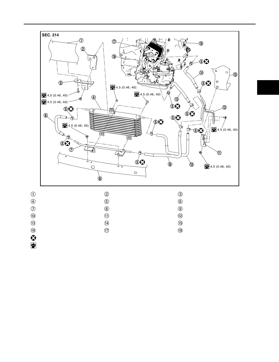
Vehicle side (Type A)

JSDIA5223GB

Bumper reinforcement

Bracket

Bracket

CVT fluid cooler

Hose clamp

CVT fluid cooler hose D

CVT fluid cooler tube assembly B

Bumper reinforcement lower

CVT fluid cooler hose C

CVT fluid cooler hose E

Bracket

CVT fluid cooler tube assembly A

CVT fluid cooler hose F

CVT fluid cooler hose B

Front side member LH

Transaxle assembly

CVT oil warmer

CVT fluid cooler tube A

: Always replace after every disassembly.

: N·m (kg-m, in-lb)

TM-644

< REMOVAL AND INSTALLATION >

[CVT: RE0F10G]

FLUID COOLER SYSTEM

Vehicle side (Type B)

Removal and Installation

INFOID:0000000010248022

REMOVAL

WARNING:

Do not remove the radiator cap when the engine is hot. Serious burns could occur from high-pressure
engine coolant escaping from the radiator. Wrap a thick cloth around the cap. Slowly push down and
turn it a quarter turn to allow built-up pressure to escape. Carefully remove the cap by pushing it down
and turning it all the way.

CAUTION:

Perform these steps after the engine coolant temperature has cooled sufficiently.
NOTE:
When removing components such as hoses, tubes/lines, etc., cap or plug openings to prevent fluid from spill-
ing.

1.

Remove the front bumper. Refer to 

EXT-19, "Removal and Installation"

.

2.

Remove the engine undercover.

JSDIA5224GB

Bumper reinforcement

Bracket

Bracket

CVT fluid cooler

Hose clamp

CVT fluid cooler hose D

CVT fluid cooler tube assembly B

CVT fluid cooler hose C

CVT fluid cooler hose E

Bracket

Radiator core support

CVT fluid cooler hose F

CVT fluid cooler tube assembly A

CVT fluid cooler hose B

Transaxle assembly

CVT oil warmer

CVT fluid cooler tube A

: Always replace after every disassembly.

: N·m (kg-m, in-lb)

: Indicates that the part is connected at points with same symbol in actual vehicle.

FLUID COOLER SYSTEM

TM-645

< REMOVAL AND INSTALLATION >

[CVT: RE0F10G]

C

E

F

G

H

I

J

K

L

M

A

B

TM

N

O

P

3.

Remove the battery. Refer to 

PG-155, "Removal and Installation"

.

4.

Remove the ECM (TCM) bracket and ECM (TCM). Refer to 

TM-625, "Removal and Installation"

.

5.

Remove the battery mounting bracket assembly and battery mounting bracket. Refer to 

PG-154,

"Exploded View"

.

6.

Remove the harness bracket mounting nuts (

) and remove

the harness bracket 

 from the vehicle.

7.

Remove hose clamps of CVT cooler hose F and B to remove the
hose on the CVT oil warmer side.

8.

Remove hose clamp (

) of CVT fluid cooler 

 to remove the

hose on the CVT fluid cooler side.

9.

Remove bracket mounting nut (

) to remove CVT cooler hose

B, C, E, and F together with CVT fluid cooler tube assembly A.

10. Remove the bracket mounting bolts (

) and remove the CVT

fluid cooler from the vehicle.

11. Remove CVT fluid cooler hose D.
12. Remove the fluid cooler tube assembly B from CVT fluid cooler.

13. Remove hose clamp of CVT cooler hose A to remove the hose

on the CVT oil warmer side.

14. Remove CVT fluid cooler tube A and CVT fluid cooler tube B.

INSTALLATION

Installation is in the reverse order of removal.

Transaxle side

JSDIA5410ZZ

JSDIA5412ZZ

JSDIA5413ZZ

JSDIA5414ZZ

TM-646

< REMOVAL AND INSTALLATION >

[CVT: RE0F10G]

FLUID COOLER SYSTEM

Refer to the followings when installing CVT fluid cooler hose.
• When installing fluid cooler tube A 

 and fluid cooler tube B 

 to

transaxle assembly.

- Contact fluid cooler tube A stopper 

 to transaxle case boss 

.

- Contact fluid cooler tube B stopper 

 to transaxle case boss 

.

• Refer to the followings when installing CVT fluid cooler hose.

CAUTION:

Never reuse hose clamps.

• Refer to the followings when installing hose clamp.

CAUTION:

Hose clamp should not interfere with the bulge of tube.

Vehicle side

• Refer to the followings when installing CVT fluid cooler hose.

CAUTION:

• Be careful not to damage CVT fluid cooler.
• Do not reuse hose clamps.

JSDIA5425ZZ

Hose 

Installation side 

tube 

Direction of paint mark

Hose insertion depth 

"A"

CVT fluid 
cooler hose 
A

CVT oil warmer

Upward

 Hose end reaches the 
end of tube.

CVT fluid cooler 
tube B

Frontward

SCIA7203E

Hose 

Installation side 

tube 

Hose clamp 

Direction of tab

Clamping position

CVT fluid 
cooler hose 
A

CVT oil warmer

Upward and 45

°


rightward

5 – 9 mm (0.20 – 0.35 in) 
(A) from hose end

CVT fluid cooler 
tube B

Frontward

JSDIA2424ZZ


Content   ..  765  766  767  768   ..