Nissan Qashqai J11. Manual - part 302


  Index      Nissan     Nissan Qashqai J11 - Service and Repair Manual


Search            


Content   ..  300  301  302  303   ..


Nissan Qashqai J11. Manual - part 302


P0107, P0108 BAROMETRIC PRESSURE SENSOR

ECM-185

< DTC/CIRCUIT DIAGNOSIS >

[MR20DD]

C

D

E

F

G

H

I

J

K

L

M

A

ECM

N

P

O

P0107, P0108 BAROMETRIC PRESSURE SENSOR

DTC Description

INFOID:0000000010702909

DTC DETECTION LOGIC

POSSIBLE CAUSE

• Harness or connectors
- The barometric pressure sensor circuit is open or shorted.
- Sensor power supply circuit 2 is shorted.
• Barometric pressure sensor
• Sensor of Sensor power supply circuit 2

FAIL-SAFE

Not applicable

DTC CONFIRMATION PROCEDURE

1.

PRECONDITIONING

If DTC Confirmation Procedure has been previously conducted, always turn ignition switch OFF and wait at
least 10 seconds before conducting the next test.

>> GO TO 2.

2.

PERFORM DTC CONFIRMATION PROCEDURE

1.

Start engine and let it idle at least 5 seconds.

2.

Check 1st trip DTC.

Is 1st trip DTC detected?

YES

>> Proceed to 

ECM-185, "Diagnosis Procedure"

.

NO-1

>> To check malfunction symptom before repair: Refer to 

GI-41, "Intermittent Incident"

.

NO-2

>> Confirmation after repair: INSPECTION END

Diagnosis Procedure

INFOID:0000000010702910

1.

CHECK BAROMETRIC PRESSURE SENSOR POWER SUPPLY-1

1.

Turn ignition switch OFF.

2.

Disconnect barometric pressure sensor harness connector.

3.

Turn ignition switch ON.

4.

Check the voltage between barometric pressure sensor harness connectors.

Is the inspection result normal?

YES

>> GO TO 7.

NO

>> GO TO 2.

2.

CHECK BAROMETRIC PRESSURE SENSOR POWER SUPPLY-2

Check the voltage between barometric pressure sensor harness connector and ground.
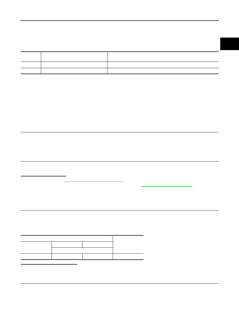
DTC No.

CONSULT screen terms

(Trouble diagnosis content)

DTC detecting condition

P0107

ABSL PRES SEN/CIRC

An excessively low voltage from the sensor is sent to ECM.

P0108

ABSL PRES SEN/CIRC

An excessively high voltage from the sensor is sent to ECM.

Barometric pressure sensor

Voltage

Connector

+

Terminal

F144

1

3

Approx. 5 V

ECM-186

< DTC/CIRCUIT DIAGNOSIS >

[MR20DD]

P0107, P0108 BAROMETRIC PRESSURE SENSOR

Is the inspection result normal?

YES

>> GO TO 5.

NO

>> GO TO 3.

3.

CHECK BAROMETRIC PRESSURE SENSOR POWER SUPPLY CIRCUIT

1.

Turn ignition switch OFF.

2.

Disconnect ECM harness connector.

3.

Check the continuity between barometric pressure sensor harness connector and ECM harness connec-
tor.

Is the inspection result normal?

YES

>> GO TO 4.

NO

>> Repair or replace malfunctioning part.

4.

CHECK SENSOR POWER SUPPLY 2

Refer to 

ECM-392, "Diagnosis Procedure"

.

Is the inspection result normal?

YES

>> INSPECTION END

NO

>> Replace malfunctioning part.

5.

CHECK BAROMETRIC PRESSURE SENSOR GROUND CIRCUIT FOR OPEN AND SHORT

1.

Turn ignition switch OFF.

2.

Disconnect ECM harness connector.

3.

Check the continuity between barometric pressure sensor harness connector and ECM harness connec-
tor.

Is the inspection result normal?

YES

>> GO TO 6.

NO

>> Repair or replace malfunctioning part.

6.

CHECK ECM GROUND CIRCUIT FOR OPEN AND SHORT

Check the voltage between ECM harness connector and ground.

+

Ground

Voltage

Barometric pressure sensor

Connector

Terminal

F144

1

Ground

Approx. 5 V

+

Continuity

Barometric pressure sensor

ECM

Connector

Terminal

Connector

Terminal

F144

1

E57

101

Existed

+

Continuity

Barometric pressure sensor

ECM

Connector

Terminal

Connector

Terminal

F144

3

E57

124

Existed

P0107, P0108 BAROMETRIC PRESSURE SENSOR

ECM-187

< DTC/CIRCUIT DIAGNOSIS >

[MR20DD]

C

D

E

F

G

H

I

J

K

L

M

A

ECM

N

P

O

Is the inspection result normal?

YES

>> INSPECTION END

NO

>> Repair or replace malfunctioning part.

7.

CHECK BAROMETRIC PRESSURE SENSOR INPUT SIGNAL CIRCUIT FOR OPEN AND SHORT

1.

Check the continuity between barometric pressure sensor harness connector and ECM harness connec-
tor.

2.

Also check harness for short to ground and short to power.

Is the inspection result normal?

YES

>> GO TO 8.

NO

>> Repair or replace malfunctioning part.

8.

CHECK BAROMETRIC PRESSURE SENSOR

Refer to 

ECM-187, "Component Inspection"

.

Is the inspection result normal?

YES

>> INSPECTION END

NO

>> Replace barometric pressure sensor. Refer to 

ECM-14, "ENGINE CONTROL SYSTEM : Compo-

nent Parts Location"

.

Component Inspection

INFOID:0000000010702911

1.

COMPONENT FUNCTION CHECK

1.

Turn ignition switch ON.

2.

Check the voltage between ECM harness connector terminals as follows.

NOTE:
Since this sensor is an absolute pressure sensor, values vary with ambient pressure and altitude.

3.

Measure the barometric pressure.
NOTE:
As the barometric pressure described on the synoptic chart is the value at sea level, compensate the
pressure with the following chart.

+

Ground

Continuity

ECM

Connector

Terminal

F15

11

Ground

Existed

E57

123

125

128

+

Barometric pressure sensor

ECM

Continuity

Connector

Terminal

Connector

Terminal

F144

2

E57

97

Existed

ECM

Connector

+

Terminal

E57

97

124

ECM-188

< DTC/CIRCUIT DIAGNOSIS >

[MR20DD]

P0107, P0108 BAROMETRIC PRESSURE SENSOR

4.

Check that the voltage is within a specified range as in the following chart.

Is the inspection result normal?

YES

>> INSPECTION END

NO

>> Replace barometric pressure sensor. Refer to 

ECM-14, "ENGINE CONTROL SYSTEM : Compo-

nent Parts Location"

.

Altitude (m)

Compensated pressure 

(hPa)

0

0

200

24

400

47

600

70

800

92

1,000

114

1,500

168

2,000

218

Barometric pressure (hPa)

Voltage (V)

800

3.1 – 3.7

850

3.3 – 3.9

900

3.5 – 4.1

950

3.8 – 4.3

1,000

4.0 – 4.6

1,050

4.2 – 4.8

JMBIA0870GB


Content   ..  300  301  302  303   ..