Nissan Qashqai J11. Manual - part 2110


  Index      Nissan     Nissan Qashqai J11 - Service and Repair Manual


Search            


Content   ..  2108  2109  2110  2111   ..


Nissan Qashqai J11. Manual - part 2110


AV

COMPONENT PARTS

AV-129

< SYSTEM DESCRIPTION >

[NAVIGATION]

C

D

E

F

G

H

I

J

K

L

M

B

A

O

P

*: 

Around View Monitor is a parking aid/convenience feature. Around View Monitor cannot completely eliminate

blind spots. Around View Monitor may not detect every object and does not warn of moving objects. Always
check surroundings before moving vehicle. Around View Monitor is not a substitute for proper backing proce-
dures. Always turn to check what is behind you before backing up.
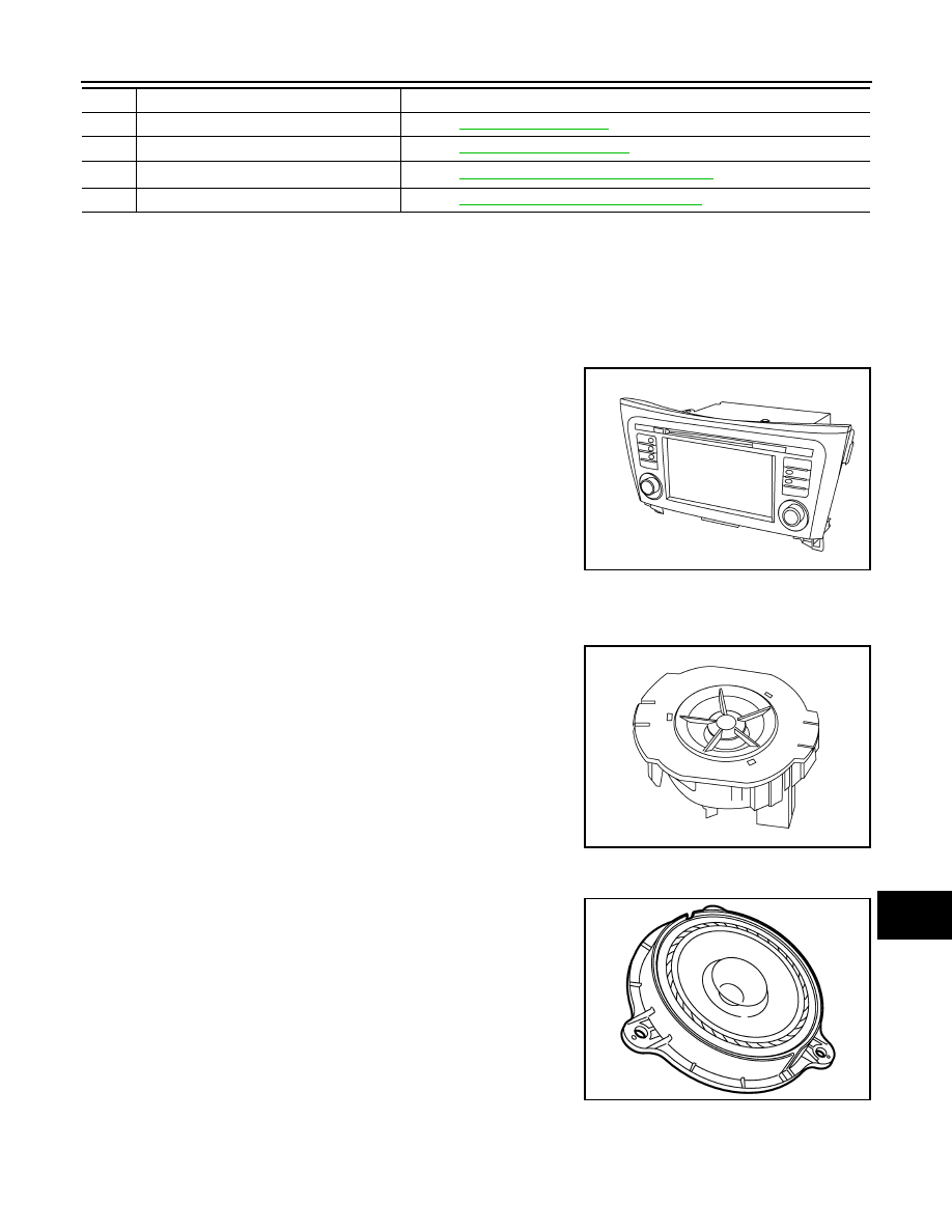
AV Control Unit

INFOID:0000000010435641

Description

• A 7-inch WVGA display, an AM/FM electronic tuner radio, CD

drive, audio amplifier are integrated into the AV control unit.

• The 7-inch display is a high resolution monitor that includes touch

panel functions.

• Music files stored in iPod

®*

/USB memory can be played using the

separate USB interface.

• Music files stored in an external audio device can be played using

the separate AUX in jack.

*

: iPod

®

 is a registered trademark of Apple, Inc. All rights reserved.

Speakers

INFOID:0000000010435642

FRONT TWEETER

• 2.5 cm (1 in) tweeters are installed in the top front corners of the

instrument panel.

• Sound signals are input from the AV control unit to output high

range sounds. 

FRONT DOOR SPEAKER

• 16.5 cm (6.5 in) speakers are installed in the bottom of the front doors.
• Sound signals are input from the AV control unit to output high, mid

and low range sounds. 

REAR DOOR SPEAKER

• 16.5 cm (6.5 in) speakers are installed in the bottom of the rear doors.

15.

AV control unit

Refer to 

AV-129, "AV Control Unit"

.

16.

Rear view camera

Refer to 

AV-131, "Rear View Camera"

.

17.

Around View

®*

 Monitor control unit

Refer to 

AV-130, "Around View Monitor Control Unit"

.

18.

USB interface and AUX in jack

Refer to 

AV-130, "USB Interface and AUX In Jack"

.

No.

Component

Function

ALNIA1590ZZ

ALNIA1593ZZ

JPNIA1454ZZ

AV-130

< SYSTEM DESCRIPTION >

[NAVIGATION]

COMPONENT PARTS

• Sound signals are input from the AV control unit to output high, mid

and low range sounds. 

USB Interface and AUX In Jack

INFOID:0000000010435643

• USB Interface and AUX in jack is installed in the console. 
• iPod

®

 and USB memory can be connected to the AV control unit through the USB interface.

• An external audio device can be connected to the AV control unit through the AUX in jack.

Steering Switches

INFOID:0000000010435644

• Steering switches are installed in the steering wheel.
• Operations for audio and hands-free phone are possible.
• Switches are connected to the combination meter.
• Combination meter is connected to the AV control unit via AV com-

munication.

Microphone

INFOID:0000000010435645

• The microphone is installed in the roof in the map lamp assembly. 
• Power is supplied from the AV control unit.

Around View Monitor Control Unit

INFOID:0000000010435646

• The around view monitor control unit is installed behind the glove

box.

• Vehicle width guide lines, predicted course line, vehicle front guid-

ing line and vehicle side line, and vehicle icon are displayed and
combined with camera images.

JPNIA1454ZZ

JSNIA7235ZZ

JPNIA1448ZZ

JSNIA5395ZZ

AV

COMPONENT PARTS

AV-131

< SYSTEM DESCRIPTION >

[NAVIGATION]

C

D

E

F

G

H

I

J

K

L

M

B

A

O

P

Rear View Camera 

INFOID:0000000010435647

• The rear view camera is installed in the back door finisher. 
• Power is supplied from the around view monitor control unit.

Side Cameras

INFOID:0000000010435648

• The side cameras are installed in the door mirrors. 
• Power is supplied from the around view monitor control unit. 

Front Camera 

INFOID:0000000010435649

• The front camera is installed in the front grille.
• Power is supplied from the around view monitor control unit.

Steering Angle Sensor

INFOID:0000000010435650

• Steering sensor is installed to the spiral cable. 
• Steering angle sends the steering signal necessary for predictive

course line via CAN communication. 

Rod Antenna, Antenna Amp., Satellite Antenna and Antenna Feeder

INFOID:0000000010435651

RADIO ANTENNA AND SATELLITE ANTENNA

JPNIA1452ZZ

JSNIA5397ZZ

JSNIA5398ZZ

JSNIA1571ZZ

AV-132

< SYSTEM DESCRIPTION >

[NAVIGATION]

COMPONENT PARTS

AM/FM radio rod antenna and antenna base are located on the rear of the roof. The antenna amp. and satel-
lite antenna are built into the antenna base.

ANTENNA FEEDER LAYOUT

AWNIA3133GB

1.

Antenna base (antenna amp. and 
satellite antenna)

2.

Rod Antenna

3.

M394

4.

M399

E1NIA0073ZZ


Content   ..  2108  2109  2110  2111   ..