Mitsubishi Outlander (2003+). Manual - part 375
TROUBLESHOOTING
SUPPLEMENTAL RESTRAINT SYSTEM (SRS)
52B-99
DIAGNOSIS PROCEDURE
STEP 1. Check the passenger's air bag module.
(Check whether the diagnosis code is reset.)
(1) Disconnect the negative battery terminal.
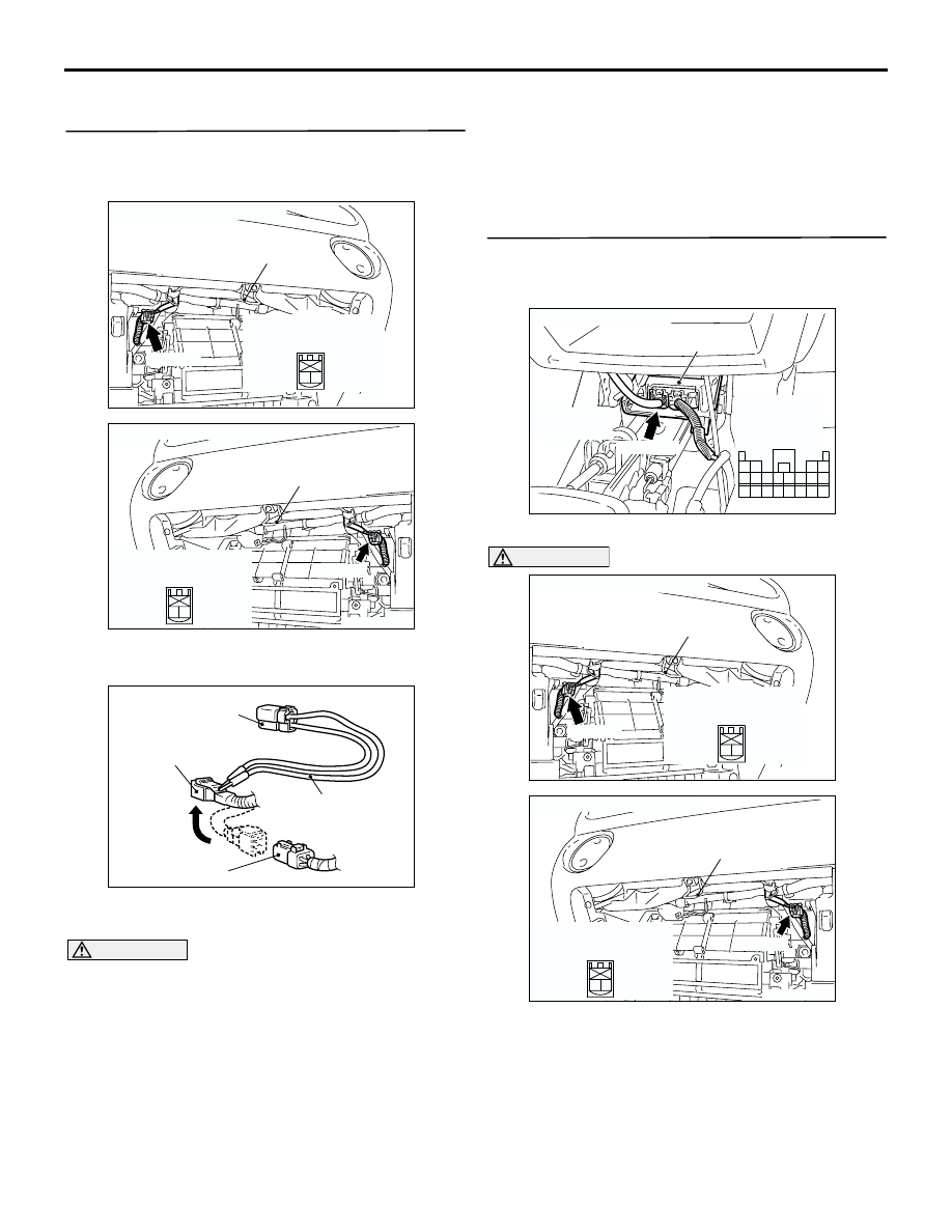
(2) Unclip passenger’s air bag module connector
C-09.
(3) Connect special tool dummy resistor (MB991865)
to special tool resistor harness (MB991866).
CAUTION
Do not insert a test probe into the terminal from
its front side directly as the connector contact
pressure may be weakened.
(4) Disconnect the passenger's air bag module
connector C-09, and insert special tool
(MB991866) into the harness side connector by
backprobing.
(5) Connect the negative battery terminal.
(6) Erase the diagnosis code memory, and check the
diagnosis code.
Q: Is diagnosis code 65 set?
YES :
Go to Step 2.
NO :
Replace the passenger's air bag module
(Refer to
). Then go to Step 3.
STEP 2. Measure the resistance at the SRS-ECU
connector C-115. (Check whether the diagnosis
code is reset.)
(1) Disconnect SRS-ECU connector C-115.
CAUTION
To prevents the air bag from deploying
unintentionally, disconnect the passenger’s air
bag module connector C-09 to short the squib
circuit.
AC301718
Connector: C-09 <LHD>
AD
C-09 (R)
Glove box striker
2 1
Harness side
connector (front view)
AC309254 AB
Connector: C-09 <RHD>
C-09 (R)
Glove box striker
2 1
Harness side
connector (front view)
AC300956AB
MB991865 (Dummy
resistor : 3
Ω)
C-09 Harness side
connector
C-09 Passenger's
air bag module connector
MB991866
(Resistor harness)
AC301661AC
Harness side
connector
(front view)
Connector: C-115
SRS-ECU
C-115 (Y)
Center lower
panel
1110 9
1
2
3
1413
12
4
5
6
16
8
15
7
17
18
19
20
AC301718
Connector: C-09 <LHD>
AD
C-09 (R)
Glove box striker
2 1
Harness side
connector (front view)
AC309254 AB
Connector: C-09 <RHD>
C-09 (R)
Glove box striker
2 1
Harness side
connector (front view)