Mitsubishi Montero (2004+). Manual - part 746


  Index      Mitsubishi     Mitsubishi Montero - service repair manual 2004 year


Search            


Content   ..  744  745  746  747   ..


Mitsubishi Montero (2004+). Manual - part 746


SYMPTOM PROCEDURES

TSB Revision

SIMPLIFIED WIRING SYSTEM (SWS)

54B-241

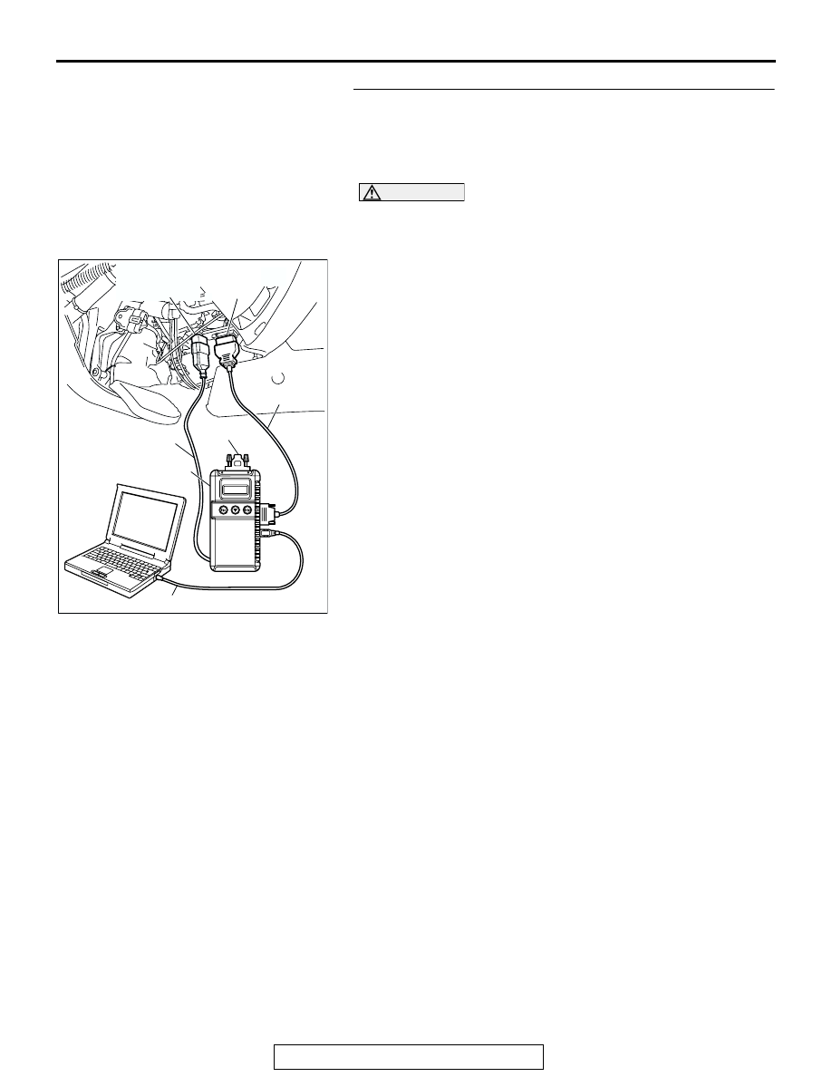
Use scan tool MB991958 to select "ECU COMM CHK" on 
the SWS monitor display.
Check the following ECUs:

• Column-ECU

• Front-ECU

CAUTION

To prevent damage to scan tool MB991958, always turn the 
ignition switch to the "LOCK" (OFF) position before con-
necting or disconnecting scan tool MB991958. 
(1) Connect the special tool. Refer to "How to connect SWS 

monito

P.54B-7

.

(2) Turn the ignition switch to the "ON" position.
(3) Operate scan tool MB991958 according to the procedure 

below to display "ECU COMM CHECK."

1. Select "SYSTEM SELECT."
2. Select "SWS."
3. Select "SWS MONITOR."
4. Select "ECU COMM CHK".

(4) Scan tool MB991958 should show "OK" on the "ECU 

COMM CHK" menus for both the "COLUMN ECU" and the 
"FRONT ECU" menus.

Q: Is "OK" displayed on the "COLUMN ECU" and "FRONT 

ECU" menu?
"OK" is displayed for all the items : 
Replace the 

front-ECU. Verify that the windshield wiper works 
normally.

"NG" is displayed on the "COLUMN ECU" menu : Refer 

to Inspection Procedure A-2 "Communication with 
column switch (column-ECU) is not possible 

P.54B-35

."

"NG" is displayed on the "FRONT ECU" menu : Refer to 

Inspection procedure A-4 "Communication with 
front-ECU is not possible 

P.54B-48

."

AC309091

MB991911

MB991827

MB991824 

AB

MB991806

MB991862

DATA LINK
CONNECTOR 
(16-PIN)

DATA LINK
CONNECTOR 
(13-PIN)

SYMPTOM PROCEDURES

TSB Revision

SIMPLIFIED WIRING SYSTEM (SWS)

54B-242

INSPECTION PROCEDURE G-3: Windshield Wiper and Washer: Any of the windshield wiper switch 
positions is defective.

NOTE: This troubleshooting procedure requires the 
use of scan tool MB991958 and SWS monitor kit 
MB991862. For details on how to use the SWS mon-
itor, refer to "How to use SWS monitor

P.54B-10

."

.

Windshield Wiper Motor Drive Circuit

AC205142AB

CONNECTOR: A-05

A-05(B)

AC205138

CONNECTOR: A-08X

AB

BATTERY

FRONT-ECU

A-08X

AC205116 AB

CONNECTOR: B-12

B-12 (B)

SYMPTOM PROCEDURES

TSB Revision

SIMPLIFIED WIRING SYSTEM (SWS)

54B-243

TECHNICAL DESCRIPTION (COMMENT)
If either of the windshield wiper switch positions is 
defective, the windshield wiper motor, column switch 
(windshield wiper and washer switch) or the 
front-ECU may be defective.

.

TROUBLESHOOTING HINTS

• The windshield wiper motor may be defective

• The column switch (windshield wiper and washer 

switch) may be defective

• The front-ECU may be defective

• The wiring harness or connectors may have 

loose, corroded, or damaged terminals, or termi-
nals pushed back in the connector

DIAGNOSIS

Required Special Tools:

• MB991223: Harness Set

• MB991958: Scan Tool (MUT-III Sub Assembly)

• MB991824: Vehicle Communication Interface (V.C.I.)

• MB991827: MUT-III USB Cable

• MB991911: MUT-III Main Harness B

• MB991813: SWS Monitor Kit

• MB991806: SWS Monitor Cartridge

• MB991812: SWS Monitor Harness (For Column-ECU)

• MB991822: Probe Harness

SYMPTOM PROCEDURES

TSB Revision

SIMPLIFIED WIRING SYSTEM (SWS)

54B-244

STEP 1. Check the input signal by using "DATA LIST" 
menu of the SWS monitor.
Turn the ignition switch to the ACC position before checking 
input signals from the windshield wiper switch.

CAUTION

To prevent damage to scan tool MB991958, always turn the 
ignition switch to the "LOCK" (OFF) position before con-
necting or disconnecting scan tool MB991958. 
(1) Connect the special tool. Refer to "How to connect SWS 

monito

P.54B-7

(2) Connect SWS monitor kit MB991862 to the data link 

connector (13-pin).

(3) Operate scan tool MB991958 according to the procedure 

below to display "COLUMN ECU."

1. Select "SYSTEM SELECT."
2. Select "SWS."
3. Select "SWS MONITOR."
4. Select "DATA LIST."
5. Select "COLUMN ECU."

(4) Check that normal conditions are displayed on the items 

described in the table below.

Q: Are normal conditions displayed for "INT WIPER SW", 

"LO WIPER SW", "HI WIPER SW" and "MIST WIPER 
SW"?
YES : 
Go to Step 2.
NO :  Refer to Inspection Procedure O-7 "ETACS-ECU 

does not receive a signal from the windshield mist 
wiper switch 

P.54B-529

."

STEP 2. Check windshield wiper motor connector B-12 for 
loose, corroded or damaged terminals, or terminals 
pushed back in the connector.
Q: Is windshield wiper motor connector B-12 in good 

condition?
YES : 
Go to Step 3.
NO :  Repair or replace the damaged component(s). Refer 

to GROUP 00E, Harness Connector Inspection 

P.00E-2

Verify that the windshield wiper operates 

normally when the windshield wiper switch is moved 
to each position.

ITEM NO.

ITEM NAME

NORMAL 
CONDITION

ITEM 05

INT WIPER SW

ON

ITEM 06

LO WIPER SW

ON

ITEM 07

HI WIPER SW

ON

ITEM 08

MIST WIPER SW

ON

AC309091

MB991911

MB991827

MB991824 

AB

MB991806

MB991862

DATA LINK
CONNECTOR 
(16-PIN)

DATA LINK
CONNECTOR 
(13-PIN)

AC205116 AD

CONNECTOR: B-12

B-12 (B)

(HARNESS SIDE)

B-12 (B)

1

2

3

4

5


Content   ..  744  745  746  747   ..