Mitsubishi Lancer Evolution IX. Manual - part 473


  Index      Mitsubishi     Mitsubishi Lancer Evolution IX - service repair manual


Search            


Content   ..  471  472  473  474   ..


Mitsubishi Lancer Evolution IX. Manual - part 473


TROUBLESHOOTING

MULTIPORT FUEL INJECTION (MPI)

13A-367

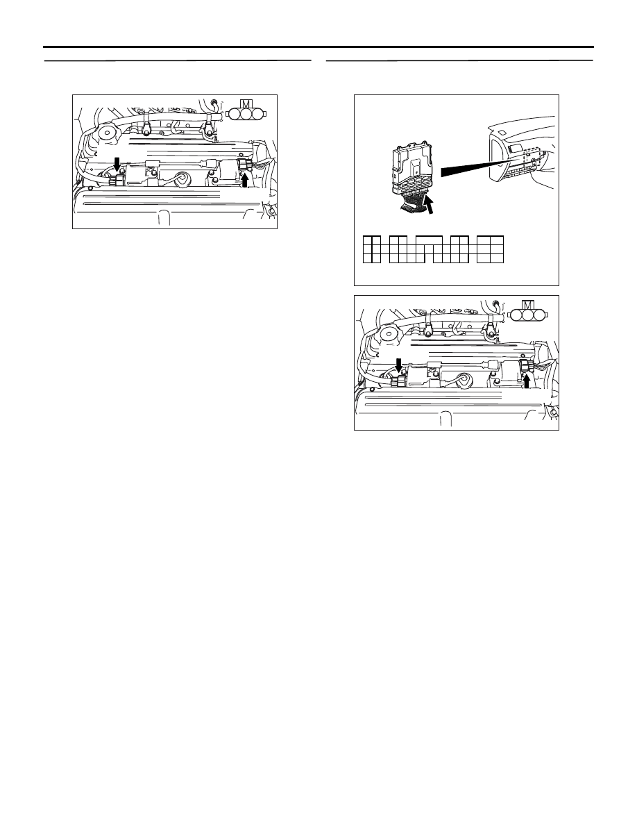
STEP 12. Perform voltage measurement at B-103 
and B-114 ignition coil connectors.

• Disconnect connector, and measure at harness 

side.

• Engine: Cranking

• Voltage between terminal No. 3 and earth.

OK: 0.5 

 4.0 V

Q: Is the check result normal? 

YES : 

Go to Step 18 .

NO : 

Go to Step 13 .

STEP 13. Perform voltage measurement at C-121 
engine-ECU connector.

• Measure engine-ECU terminal voltage.

• Disconnect B-103 and B-114 ignition coil connec-

tors.

• Engine: Cranking

• Voltage between terminal No. 11 and earth, also 

between terminal No. 12 and earth.

OK: 0.5 

 4.0 V

Q: Is the check result normal? 

YES : 

Go to Step 14 .

NO : 

Go to Step 15 .

AK305047

1

2

3

Connector : B-103, B-114

B-114(GR)

B-103(GR)

AB

Harness side 
connector

AK502033

2

3

4

5

6

7

8

9

11

12

13

14

15

16

17

18

19

20

30

21

22

23

24

25

26

27

28

29

31

32

33

34

35

1

10

C-121 (GR)

AB

Connector: C-121

Harness side connector

AK305047

1

2

3

Connector : B-103, B-114

B-114(GR)

B-103(GR)

AB

Harness side 
connector

TROUBLESHOOTING

MULTIPORT FUEL INJECTION (MPI)

13A-368

STEP 14. Connector check: C-121 engine-ECU 
connector

Q: Is the check result normal? 

YES : 

Check and repair harness between B-114 

(terminal No. 3) ignition coil connector and 
C-121 (terminal No. 12) engine-ECU 
connector, also between B-103 (terminal 
No. 3) ignition coil connector and C-121 
(terminal No. 11) engine-ECU connector.

• Check output line for open circuit.

NO : 

Repair or replace the connector.

STEP 15. Connector check: C-121 engine-ECU 
connector

Q: Is the check result normal? 

YES : 

Go to Step 16 .

NO : 

Repair or replace the connector.

AK502033

2

3

4

5

6

7

8

9

11

12

13

14

15

16

17

18

19

20

30

21

22

23

24

25

26

27

28

29

31

32

33

34

35

1

10

C-121 (GR)

AB

Connector: C-121

Harness side connector

AK305047

1

2

3

Connector : B-103, B-114

B-114(GR)

B-103(GR)

AB

Harness side 
connector

AK502033

2

3

4

5

6

7

8

9

11

12

13

14

15

16

17

18

19

20

30

21

22

23

24

25

26

27

28

29

31

32

33

34

35

1

10

C-121 (GR)

AB

Connector: C-121

Harness side connector

TROUBLESHOOTING

MULTIPORT FUEL INJECTION (MPI)

13A-369

STEP 16. Check harness between B-114 (terminal 
No. 3) ignition coil connector and C-121 (terminal 
No. 12) engine-ECU connector, also between 
B-103 (terminal No. 3) ignition coil connector and 
C-121 (terminal No. 11) engine-ECU connector.

• Check output line for short circuit.

Q: Is the check result normal? 

YES : 

Go to Step 17 .

NO : 

Repair the damaged harness wire.

STEP 17. Check the trouble symptoms.

Q: Does trouble symptom persist?

YES : 

Replace the engine-ECU.

NO : 

Intermittent malfunction (Refer to GROUP 
00 

− How to Use 

Troubleshooting/Inspection Service Points 

P.00-5

).

STEP 18. Perform resistance measurement at 
B-103 and B-114 ignition coil connectors.

• Disconnect connector, and measure at harness 

side.

• Resistance between terminal No. 2 and earth.

OK: 2 

 or less

Q: Is the check result normal? 

YES : 

Go to Step 19 .

NO : 

Check and repair harness between B-103 

(terminal No. 2) ignition coil connector and 
body earth, also between B-114 (terminal 
No. 2) ignition coil connector and body 
earth.

• Check earthing line for open circuit 

and damage.

AK305047

1

2

3

Connector : B-103, B-114

B-114(GR)

B-103(GR)

AB

Harness side 
connector

AK502033

2

3

4

5

6

7

8

9

11

12

13

14

15

16

17

18

19

20

30

21

22

23

24

25

26

27

28

29

31

32

33

34

35

1

10

C-121 (GR)

AB

Connector: C-121

Harness side connector

AK305047

1

2

3

Connector : B-103, B-114

B-114(GR)

B-103(GR)

AB

Harness side 
connector

TROUBLESHOOTING

MULTIPORT FUEL INJECTION (MPI)

13A-370

STEP 19. Check harness between C-208 (terminal 
No. 2) ignition switch connector and B-10X 
(terminal No. 2) ignition coil relay connector.

NOTE: Before checking harness, check intermediate 
connectors C-123, C-211 and C-214, and repair if 
necessary.

• Check power supply line for damage.

Q: Is the check result normal? 

YES : 

Go to Step 20 .

NO : 

Repair the damaged harness wire.

STEP 20. Check harness between battery and 
B-10X (terminal No. 1) ignition coil relay 
connector.

NOTE: Before checking harness, check intermediate 
connector C-31 and repair if necessary.

• Check power supply line for damage.

Q: Is the check result normal? 

YES : 

Go to Step 21 .

NO : 

Repair the damaged harness wire.

STEP 21. Check harness between B-10X 
(terminal No. 4) ignition coil relay connector and 
B-103 (terminal No. 1) ignition coil connector, 
also between B-10X (terminal No. 4) ignition coil 
relay connector and B-114 (terminal No. 1) 
ignition coil connector.

• Check power supply line for damage.

Q: Is the check result normal? 

YES : 

Go to Step 22 .

NO : 

Repair the damaged harness wire.

1

2

3

4

5

6

AK305448

Harness side 
connector

Connector: C-208

C-208

AB

AK305279

2

1

3

4

Relay box's 
triangle marks

AB

B-10X(B)

Harness side
connector

Connector: B-10X

AK305279

2

1

3

4

Relay box's 
triangle marks

AB

B-10X(B)

Harness side
connector

Connector: B-10X

AK305279

2

1

3

4

Relay box's 
triangle marks

AB

B-10X(B)

Harness side
connector

Connector: B-10X

AK305047

1

2

3

Connector : B-103, B-114

B-114(GR)

B-103(GR)

AB

Harness side 
connector


Content   ..  471  472  473  474   ..