Mitsubishi Lancer Evolution IX. Manual - part 472


  Index      Mitsubishi     Mitsubishi Lancer Evolution IX - service repair manual


Search            


Content   ..  470  471  472  473   ..


Mitsubishi Lancer Evolution IX. Manual - part 472


TROUBLESHOOTING

MULTIPORT FUEL INJECTION (MPI)

13A-363

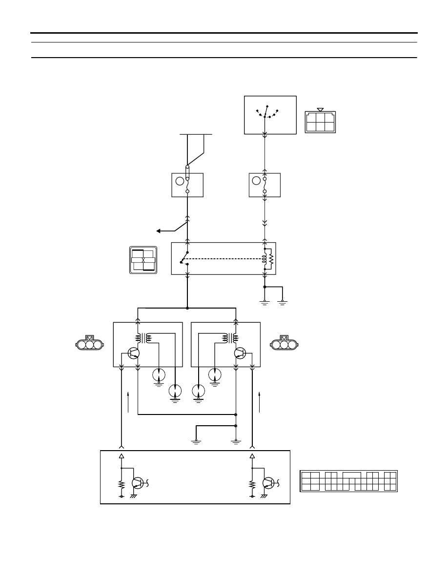
Inspection Procedure 31: Ignition Circuit System <R. H. drive vehicles>

1 2 3

1 2 3

1

2

3

4

AK501855

1 2 3
4 5 6

2

3 4

5 6

7 8

9

11 12 13 14 15 16 17 18 19 20

30

21 22 23

24 25

26 27 28 29

3132 33

34 35

1

10

LOCK

ACC

IG1

R

IG2

ST

Engine-ECU

Ignition coil 2

B-114

(MU802064)

Ignition coil 1

B-103

(MU802064)

2

1

1

3

3

2

11

12

Ignition switch

Battery

C-208

W

W

B

B

B

B-Y

B

B

B

B-G

2

1

10A

2

W

1

4

3

6

C-211

C-31

13

10

C-214

C-123

9

Ignition circuit

C-121

(MU803784)

Wire colour code
B: Black  LG: Light green  G: Green  L: Blue  W: White  Y: Yellow  SB: Sky blue  BR: Brown  O: Orange  GR: Gray
R: Red  P: Pink  V: Violet  PU: Purple

AB

Spark
plug

8

20A

B-Y

B-W

B-R

J/B

B-Y

W-R

W-R

W-R

Relay
box

OFF

ON

Engine
control
system

Ignition
coil relay

B-10X

TROUBLESHOOTING

MULTIPORT FUEL INJECTION (MPI)

13A-364

OPERATION

• The battery voltage is applied to the ignition coil 

relay (terminal No. 2) from the ignition switch and 
is earthed to the vehicle body from the ignition 
coil relay (terminal No. 3).

• The battery voltage is applied to the ignition coil 

relay (terminal No. 1) from the battery and is 
earthed to the vehicle body from the ignition coil 
(terminal No. 2).

• A power voltage of 12 V is applied to the ignition 

coil output terminal (terminal No. 3) from the 
engine-ECU (terminal No. 11 and No. 12).

FUNCTION

• When the engine-ECU makes the power transis-

tor in the unit be in "OFF" position, the battery 
voltage in the unit is applied to the power transis-
tor unit, and that makes the power transistor unit 
be in "ON" position. The engine-ECU makes the 
power transistor in the unit be in "ON", and that 
makes the power transistor unit be in "OFF" posi-
tion.

• In response to the signal from the engine-ECU, 

the power transistor unit is in "ON" position. The 
primary current is going to the ignition coil. When 
the power transistor unit is in "OFF" position, the 
primary current is interrupted and high voltage is 
generated in the secondary coil.

PROBABLE CAUSES

• Failed ignition coil

• Failed ignition coil relay

• Failed spark plug

• Failed spark plug cable

• Open/short circuit in ignition primary circuit or 

loose connector contact

• Failed engine-ECU

DIAGNOSIS PROCEDURE

STEP 1. Check spark plug cable itself.

• Check spark plug cable itself (Refer to GROUP 

16 

− Ignition System − On-vehicle Service 

P.16-29

).

Q: Is the check result normal?

YES : 

Go to Step 2 .

NO : 

Replace the spark plug cable.

STEP 2. Check spark plug.

Q: Is the check result normal?

YES : 

Go to Step 3 .

NO : 

Replace the spark plug.

STEP 3. Connector check: B-103 and B-114 
ignition coil connectors

Q: Is the check result normal? 

YES : 

Go to Step 4 .

NO : 

Repair or replace the connector.

STEP 4. Check ignition coil itself.

• Check ignition coil itself (Refer to GROUP 16 − 

Ignition System 

 On-vehicle Service 

P.16-28

).

Q: Is the check result normal? 

YES : 

Go to Step 5 .

NO : 

Replace the ignition coil.

STEP 5. Perform voltage measurement at B-103 
and B-114 ignition coil connectors.

• Disconnect connector, and measure at harness 

side.

• Ignition switch: "ON" 

• Voltage between terminal No. 1 and earth.

OK: System voltage

Q: Is the check result normal? 

YES : 

Go to Step 12 .

NO : 

Go to Step 6 .

AK305047

1

2

3

Connector : B-103, B-114

B-114(GR)

B-103(GR)

AB

Harness side 
connector

AK305047

1

2

3

Connector : B-103, B-114

B-114(GR)

B-103(GR)

AB

Harness side 
connector

TROUBLESHOOTING

MULTIPORT FUEL INJECTION (MPI)

13A-365

STEP 6. Connector check: B-10X ignition coil 
relay connector

Q: Is the check result normal? 

YES : 

Go to Step 7 .

NO : 

Repair or replace the connector.

STEP 7. Check ignition coil relay.

• Check ignition coil relay (Refer to GROUP 16 − 

Ignition System 

 On-vehicle Service 

P.16-28

).

Q: Is the check result normal? 

YES : 

Go to Step 8 .

NO : 

Replace the ignition coil relay.

STEP 8. Perform voltage measurement at B-10X 
ignition coil relay connector.

• Remove relay, and measure at relay box side.

• Ignition switch: "ON" 

• Voltage between terminal No. 2 and earth.

OK: System voltage

Q: Is the check result normal? 

YES : 

Go to Step 10 .

NO : 

Go to Step 9 .

STEP 9. Connector check: C-208 ignition switch 
connector

Q: Is the check result normal? 

YES : 

Check intermediate connectors C-123, 

C-211 and C-214, and repair if necessary. If 
intermediate connectors are normal, check 
and repair harness between C-208 (terminal 
No. 2) ignition switch connector and B-10X 
(terminal No. 2) ignition coil relay connector.

• Check power supply line for 

open/short circuit.

NO : 

Repair or replace the connector.

AK305279

2

1

3

4

Relay box's 
triangle marks

AB

B-10X(B)

Harness side
connector

Connector: B-10X

AK305279

2

1

3

4

Relay box's 
triangle marks

AB

B-10X(B)

Harness side
connector

Connector: B-10X

1

2

3

4

5

6

AK305448

Harness side 
connector

Connector: C-208

C-208

AB

AK305279

2

1

3

4

Relay box's 
triangle marks

AB

B-10X(B)

Harness side
connector

Connector: B-10X

TROUBLESHOOTING

MULTIPORT FUEL INJECTION (MPI)

13A-366

STEP 10. Perform resistance measurement at 
B-10X connector.

• Remove relay, and measure at relay box side.

• Resistance between terminal No. 3 and earth.

OK: 2 

 or less

Q: Is the check result normal? 

YES : 

Go to Step 11 .

NO : 

Check and repair harness between B-10X 

(terminal No. 3) ignition coil relay connector 
and body earth.

• Check earthing line for open circuit 

and damage.

STEP 11. Perform voltage measurement at B-10X 
ignition coil relay connector.

• Remove relay, and measure at relay box side.

• Voltage between terminal No. 1 and earth.

OK: System voltage

Q: Is the check result normal? 

YES : 

Check and repair harness between B-10X 

(terminal No. 4) ignition coil relay connector 
and B-103 (terminal No. 1) ignition coil 
connector, also between B-10X (terminal 
No. 4) ignition coil relay connector and 
B-114 (terminal No. 1) ignition coil 
connector.

• Check power supply line for 

open/short circuit.

NO : 

Check intermediate connector C-31 and 

repair if necessary. If intermediate 
connector is normal, check and repair 
harness between B-10X (terminal No. 1) 
ignition coil relay connector and battery.

• Check power supply line for 

open/short circuit.

AK305279

2

1

3

4

Relay box's 
triangle marks

AB

B-10X(B)

Harness side
connector

Connector: B-10X

AK305279

2

1

3

4

Relay box's 
triangle marks

AB

B-10X(B)

Harness side
connector

Connector: B-10X

AK305047

1

2

3

Connector : B-103, B-114

B-114(GR)

B-103(GR)

AB

Harness side 
connector


Content   ..  470  471  472  473   ..