Mitsubishi Lancer Evolution IX. Manual - part 303
MB991561
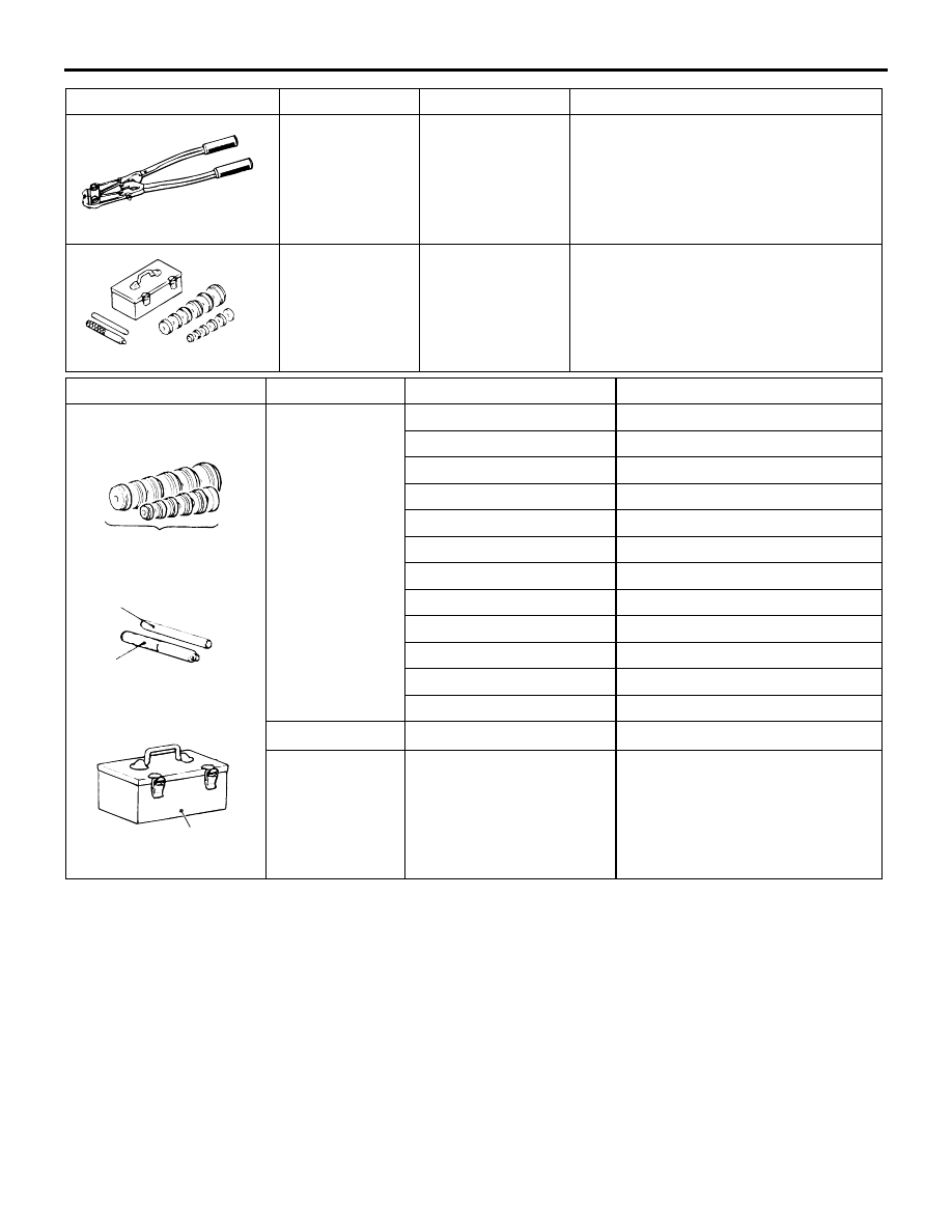
SPECIAL TOOLS
FRONT AXLE
26-5
MB991561
Boot band
crimping tool
BJ boot (resin boot) band installation
MB990925
MB990925
Bearing and oil
seal installer set
• Removal of the wheel bearing
• Removal and installation of the
centre bearing
• Press-fitting of the dust seal outer,
inner
Tool
Type
Tool number
O D mm
ACX02372
A
B
C
Brass bar
Bar (snap-in type)
Tool box
MB990925
AC
Installer adapter
A
MB990926
39.0
MB990927
45.0
MB990928
49.5
MB990929
51.0
MB990930
54.0
MB990931
57.0
MB990932
61.0
MB990933
63.5
MB990934
67.5
MB990935
71.5
MB990936
75.5
MB990937
79.0
B
MB990938
−
C
MB990939
−
Tool
Number
Name
Use