Mitsubishi Lancer Evolution 7. Manual - part 282


  Index      Mitsubishi     Mitsubishi Lancer Evolution 7 - service repair manual


Search            


Content   ..  280  281  282  283   ..


Mitsubishi Lancer Evolution 7. Manual - part 282


REAR AXLE -

Troubleshooting <AYC>

27B-13

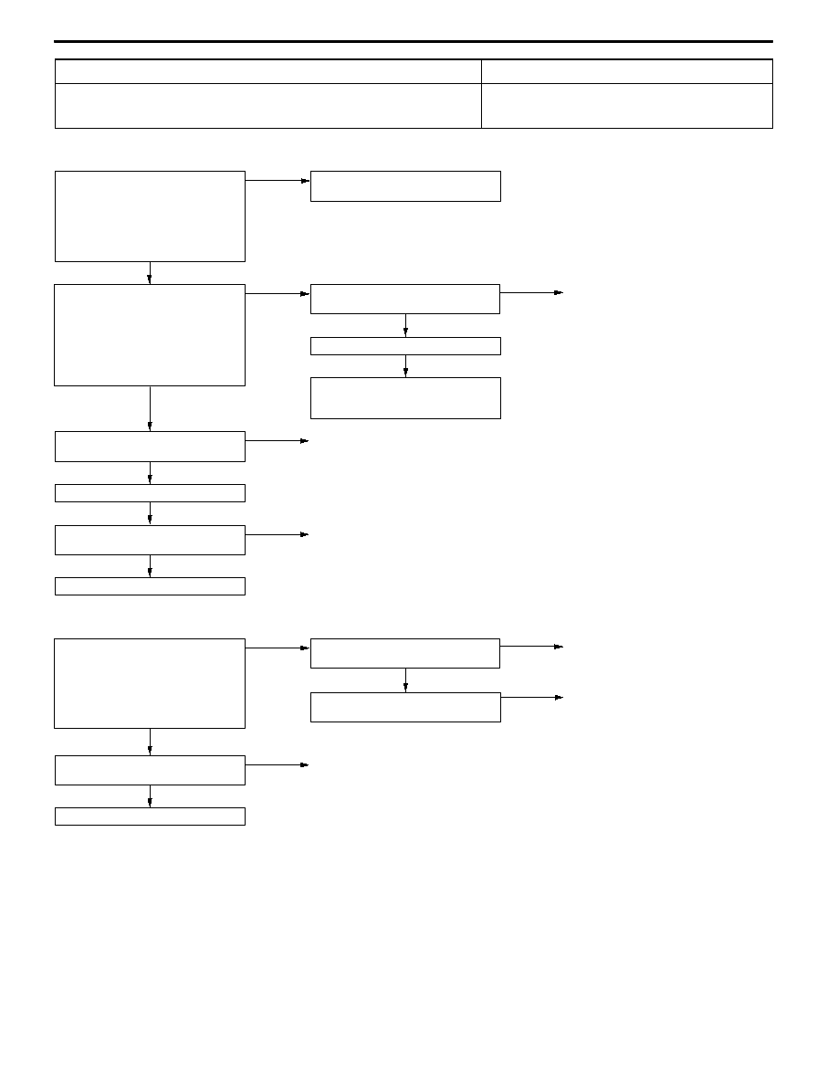
Code No. 73 Directional control valve (left) system

Probable cause

This code is output when the directional control valve (left) control circuit is open-

or short-circuited.

D

Defective directional control valve (left)

D

Defective harness or connector

D

Defective 4WD-ECU

<Vehicles with ACD + AYC>

NG

Check and repair the harness between

directional control valve (left) and body

earth.

OK

Check the trouble symptom.

OK

Replace 4WD-ECU.

NG

Checktheharnessbetweendirectional

control valve (left) and 4WD-ECU.

NG

Repair

OK

Check the trouble symptom.

OK

Check the following connectors:

C-44, C-130*, C-134, F-24, F-25

NG

Repair

OK

Measure at directional control valve

(left) connector F-25.
D

Disconnect the connector and

measure at the directional control

valve side.

D

Resistance between 1 and body

earth

OK: 2 Ω or less

NG

Check the following connectors:

F-25, F-24

NG

Repair

Measure at directional control valve

(left) connector F-25.
D

Disconnect the connector and

measure at the directional control

valve side.

D

Resistance between 1 and 2

OK: 19 - 21 Ω or less

NG

Replace the hydraulic unit. (Refer to

P27B-61.)

*: L.H. drive vehicles

<Vehicles with ACD>

OK

Check and repair the harness between

4WD-ECU and body earth.

Measure at 4WD-ECU connector

C-43.
D

Disconnect the connector and

measure at the harness side.

D

Resistance between 50 and body

earth

OK: 2 Ω or less

NG

Check the following connector:

C-43

NG

Repair

OK

Replace 4WD-ECU.

OK

Check the following connector:

C-43

NG

Repair

NG

Repair

REAR AXLE -

Troubleshooting <AYC>

REAR AXLE -

Troubleshooting <AYC>

27B-14

INSPECTION CHART FOR TROUBLE SYMPTOMS

Trouble symptom

Inspection

procedure No.

Reference

page

Communication between MUT-II and the whole system is not possible.

1

Refer to

GROUP 22

Communication between MUT-II and 4WD-ECU is not possible.

2

GROUP 22.

3 ACD mode indicator lamps do not light up when the ignition key is turned to “ON”

(engine stationary).

3

3 ACD mode indicator lamps remain lit up after the engine has started.

4

AYC is inoperative.
Unable to start or accelerate on slippery road surfaces.

5

27B-14

Rear tires are noisy during low-speed cornering.
Vehicle skews.

6

27B-15

Noise is produced from the torque transfer differential during turning.

7

27B-15

INSPECTION PROCEDURE FOR TROUBLE SYMPTOMS

INSPECTION PROCEDURE 5

AYC is inoperative.
Unable to start or accelerate on slippery road surfaces.

Probable cause

The hydraulic oil level is probably low, there is an oil leak, the hydraulic unit is defective,

or the torque transfer differential is defective.

D

Low hydraulic oil level

D

Oil leak

D

Defective hydraulic unit

D

Defective torque transfer differential

NOTE

This symptom is limited only when the diagnosis code is correct.

NG

Replace the hydraulic unit. (Refer to

P.27B-61.)

NG

Add fluid. (Refer to P.27B-19.)

OK

Repair

Check the trouble symptom.

NO

Replacethetorquetransferdifferential.

OK

Is foreign matter trappedin thehydrau-

lic line?

YES

Repair

OK

Check the fluid level.

(Refer to P.27B-19.)

Check the hydraulic pressure line for

leak.

OK

Add gear oil. (Refer to P.27B-16.)

OK

Check hydraulic pressure.

(Refer to P.27-21.)

NG

Bleed the system of air.

(Refer to P.27-19.)

Check the gear oil level. (Refer to

P.27B-16.)

NG

Check for oil leak.

NG

Repair

Check the AYC for operation.

(Refer to P.27B-20.)

Check the trouble symptom.

OK

OK

NG

Normal

NG

NG

REAR AXLE -

Troubleshooting <AYC>

27B-15

INSPECTION PROCEDURE 6

Rear tires are noisy during low-speed cornering.

Vehicle skews.

Probable cause

The hydraulic unit or torque transfer differential is probably defective.

D

Defective hydraulic unit

D

Defective torque transfer differential

NOTE

This symptom is limited only when the diagnosis code is correct.

NG

Replace the hydraulic unit. (Refer to

P.27B-61.)

NG

Add fluid. (Refer to P.27B-19.)

OK

Repair

Check the trouble symptom.

NO

Replacethetorquetransferdifferential.

OK

Is foreign matter trappedin thehydrau-

lic line?

YES

Repair

Check the fluid level.

(Refer to P.27B-19.)

Check the hydraulic pressure line for

leak.

OK

Check hydraulic pressure.

(Refer to P.27-21.)

NG

Bleed the system of air.

(Refer to P.27-19.)

Check the AYC for operation.

(Refer to P.27B-20.)

Check the trouble symptom.

OK

NG

NG

NG

INSPECTION PROCEDURE 7

Noise is produced from the torque transfer differential

during turning

Probable cause

The torque transfer differential is probably defective.

D

Defective torque transfer differential

NOTE

This symptom is limited only when the diagnosis code is correct.

NG

Replace the gear oil of the torque transfer differential. (Refer to

P.27B-17.)

Replace the gear oil of the torque transfer differential. (Refer to

P.27B-17.)

Normal

Replace the gear oil of the torque transfer differential. (Refer to

P.27B-17.)

Replace the torque transfer differential.

Check the trouble symptom.

OK

NG

NG

MUT-II Actuator test
D

No. 06 Clutch operation check (left side) 5 times

D

No. 07 Clutch operation check (right side) 5 times

D

Steering wheel on neutral position

D

Drive straight in 20 km/h or less

MUT-II Actuator test
D

No. 06 Clutch operation check (left side) 5 times

D

No. 07 Clutch operation check (right side) 5 times

D

Steering wheel on neutral position

D

Drive straight in 20 km/h or less

Check the trouble symptom.

Normal

REAR AXLE -

On-vehicle Service

27B-16

DATA LIST REFERENCE TABLE

For check, refer to GROUP 22.

ACTUATOR TEST REFERENCE TABLE

For check, refer to GROUP 22.

CHECK AT 4WD-ECU TERMINALS

For check, refer to GROUP 22.

ON-VEHICLE SERVICE

REAR AXLE TOTAL BACKLASH CHECK

1. Park the vehicle on a flat, level surface.

2. Move the transmission control lever to the neutral position.

Apply the parking brake. Raise the vehicle on a jack.

3. Turn the companion flange clockwise as far as it will go.

Make the mating mark on the dust cover of the companion

flange and on the differential carrier.

4. Turn the companion flange anti-clockwise as far as it

will go, and measure the amount of distance the mating

marks moved.
Limit: 6 mm

5. If the backlash exceeds the limit value, replace the

differential carrier assembly.

GEAR OIL LEVEL CHECK

<Vehicles with mechanical LSD>
1. Remove the filler plug.

2. Check that the gear oil level is within the specified range

from the bottom end of the filler plug hole.

3. If the gear oil level exceeds the standard value, add the

specified gear oil up to the bottom end of the filler plug

hole.
Specified gear oil:

Hypoid gear oil

MITSUBISHI Genuine Gear Oil Part No. 8149630

EX, CASTROL HYPOY LS (GL-5, SAE 90),

SHELL-LSD (GL-5, SAE 80W - 90) or equivalent

4. Fit the filler plug and tighten it to the specified torque.

Tightening torque: 49 ± 9 N·m

Mating marks

Upper

limit

Lower

limit

Gear oil

8 mm


Content   ..  280  281  282  283   ..