Mitsubishi Lancer Evolution 7. Manual - part 280
REAR AXLE -
Special Tools
27B-5
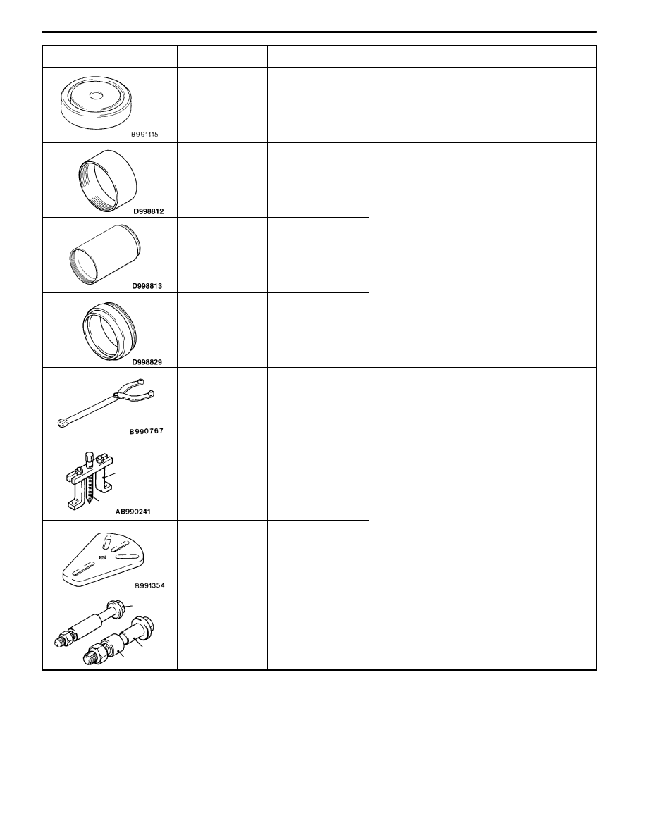
Tool
Use
Name
Number
MB991115
Oil seal installer
Press-fitting of oil seal
(AYC differential: used in combination with
MB990938)
MD998812
Installer cap
Press-fitting of oil seal
(torque transfer mechanism of vehicles with
AYC)
MD998813
Installer100
MD998829
Installer
adapter
(60)
MB990767
Front
hub
and
flange yoke holder
Removal, installation of the drive shaft nut
A
B
MB990241
A: MB990242
B: MB990244
Rear axle shaft
puller
A: Puller shaft
B: Puller bar
D
Removal of drive shaft
D
Removal of rear hub assembly
MB991354
Puller body
A
C
B
00005697
A: MB991017
B: MB990998
C: MB991000
A,B:Front hub re-
mover and in-
staller
C: Spacer
D
Temporary fixing of wheel bearing
D
Measurement of wheel bearing rotation
starting torque
D
Measurement of wheel bearing axial play
Use MB991000 (component of MB990998)
for the spacer.