Mitsubishi Lancer Evolution 7. Manual - part 73
WIRING HARNESS CONFIGURATION DIAGRAMS
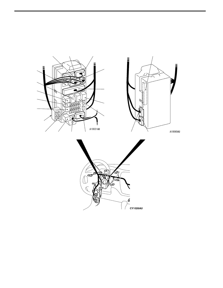
JUNCTION BLOCK
(Front view)
(Rear view)
Dedicated
fuse
C-208
C-209
C-210
C-226
C-220
C-219 C-218
C-216
C-228
C-227
C-211
C-213
C-214
C-215
C-225
C-224
C-223
C-222
C-221
B-23
C-214 (5)
Defogger relay
C-215 (5)
Blower relay
C-216 (15)
Floor wiring harness (LH) and J/B
combination
C-218 (3)
Roof wiring harness (RH) and J/B
combination
C-219 (4)
Rear fog lamp relay
C-220 (4)
No connection
C-221 (4)
Fuel pump relay 2
C-222 (4)
Intercooler water spray relay
C-223 (4)
Fuel pump relay 1
C-224 (5)
Power window relay
C-225 (2)
No connection
C-226 (20)
ETACS-ECU
C-227 (24)
ETACS-ECU
C-228 (24-GR) ETACS-ECU
C-230 (5)
Steering wheel sensor