Mazda Automatic Transaxle JA5AX-EL. Manual - part 3
K1–2
OUTLINE, AUTOMATIC TRANSAXLE
SUPPLEMENTAL SERVICE INFORMATION
A6E570201034301
•
The following changes have been made since publication of the Automatic Transaxle Workshop Manual JA5A-
EL (1738-1*-02D.).
DIRECT CLUTCH DISASSEMBLY
•
Number of drive/driven plates have been modified.
DIRECT CLUTCH ASSEMBLY
•
Assembly procedure has been modified.
End Of Sie
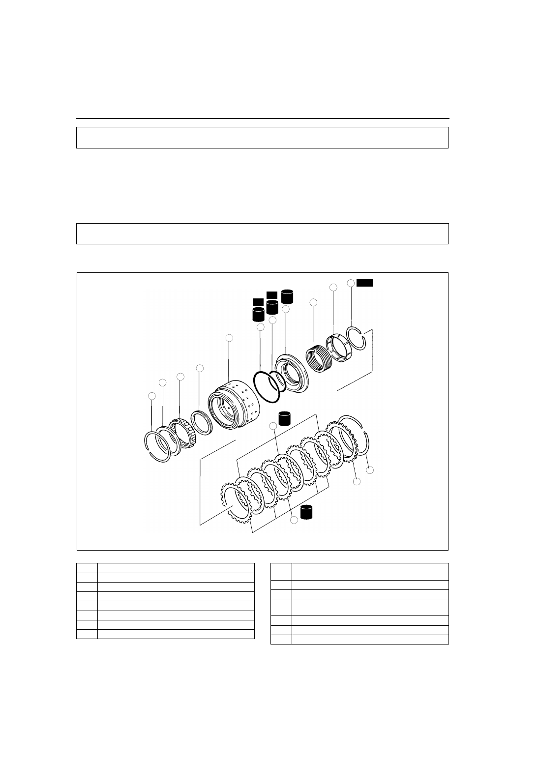
DIRECT CLUTCH DISASSEMBLY
A6E571419500310
1. Disassemble in the order indicated in the table.
.
OUTLINE
AUTOMATIC TRANSAXLE
ATF
TF
ATF
TF
ATF
TF
9
4
3
1
2
10
SST
R
R
15
14
13
11
12
ATF
TF
ATF
TF
8
5
6
7
A6E5614A902
1
Snap ring
2
Retainer
3
One-way clutch
4
Needle bearing
5
Snap ring
6
Retaining plate
7
Drive plate
8
Driven plate
9
Snap ring
(See
K1–3 Snap Ring Disassembly Note
)
10
Spring retainer
11
Return spring
12
Direct piston
(See
K1–3 Direct Piston Disassembly Note
13
O-ring
14
O-ring
15
Direct clutch drum