Mazda CX 7. Manual - part 209


  Index      Mazda     Mazda CX 7 - service repair manual 2007 year


Search            


Content   ..  207  208  209  210   ..


Mazda CX 7. Manual - part 209


CONVENTIONAL BRAKE SYSTEM 

04-11–7

04-11

Brake Pedal Removal Note

1. Remove the console panel. (See 09-17-15 CONSOLE PANEL REMOVAL/INSTALLATION.)
2. Remove the console. (See 09-17-13 CONSOLE REMOVAL/INSTALLATION.)
3. Remove the front scuff plate inner. (See 09-17-19 FRONT SCUFF PLATE REMOVAL/INSTALLATION.)
4. Remove the front side trim. (See 09-17-18 FRONT SIDE TRIM REMOVAL/INSTALLATION.)
5. Remove the Glove Compartment. (See 09-17-8 GLOVE COMPARTMENT REMOVAL/INSTALLATION.)
6. Remove the lower panel. (See 09-17-9 LOWER PANEL REMOVAL/INSTALLATION.)
7. Remove the hood release lever. (See 09-14-25 HOOD LATCH AND RELEASE LEVER REMOVAL/

INSTALLATION.)

8. Remove the lower panel. (See 09-17-9 LOWER PANEL REMOVAL/INSTALLATION.)
9. Remove the a-pillar lower trim. (See 09-17-16 A-PILLAR LOWER TRIM REMOVAL/INSTALLATION.)

10. Remove the a-pillar trim. (See 09-17-15 A-PILLAR TRIM REMOVAL/INSTALLATION.)
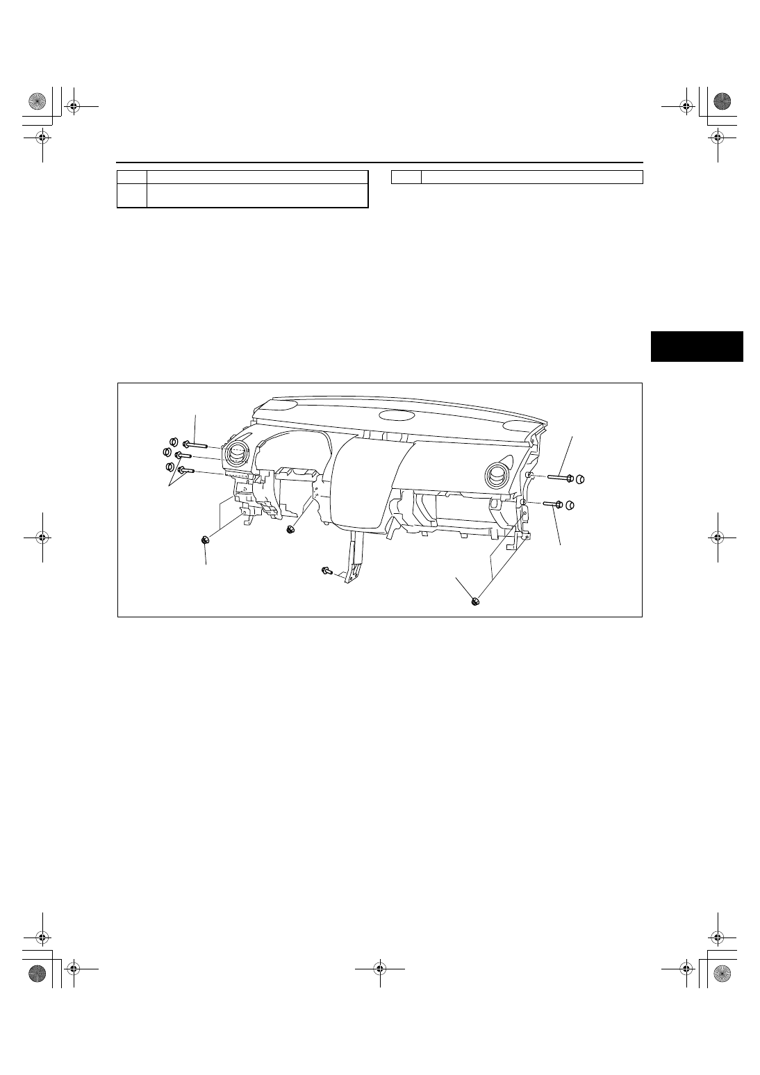
11. Remove the dashboard installation bolts and nuts as shown in the figure.

7

Bolt, nut

8

Brake pedal
(See 04-11-7 Brake Pedal Removal Note.)

9

Pedal pad

15.7—22.5 
{1.61—2.29, 
11.6—16.5}

N·m {kgf·m,  ft·lbf}

15.7—22.5 
{1.61—2.29, 
11.6—16.5}

15.7—22.5 
{1.61—2.29, 
11.6—16.5}

15.7—22.5 
{1.61—2.29, 
11.6—16.5}

15.7—22.5 
{1.61—2.29, 
11.6—16.5}

15.7—22.5 
{1.61—2.29, 
11.6—16.5}

acxuuw00001563

1871-1U-06B(04-11).fm  7 ページ  2006年3月15日 水曜日 午前11時13分

CONVENTIONAL BRAKE SYSTEM 

04-11–8

12. Lift up the upper side of the dashboard and move 

it 20 mm {0.78 in} towards the vehicle rear.

Caution

• If the dashboard is moved towards the 

vehicle rear excessively, the wiring 
harness could be damaged. Mark the 
position and verify the distance when 
moving the dashboard.

13. Move the power brake unit to the vehicle front 

where the power brake unit fork does not interfere 
with the brake pedal arm.

14. Remove the brake pedal.

Brake Switch Installation Note

1. Inspect the brake pedal. (See 04-11-4 BRAKE PEDAL INSPECTION.)
2. With the brake pedal fully released, insert a new brake switch into the installation hole on the lock unit.
3. Secure the brake switch by turning it 

counterclockwise 45

°.

Brake Switch Connector Installation Note

1. Inspect the brake pedal. (See 04-11-6 BRAKE PEDAL REMOVAL/INSTALLATION.)
2. With the brake pedal in its original position, install the brake switch to the brake switch connector. 

End Of Sie

WM: BRAKE SWITCH

MARK

20 mm {0.78 in}

DASHBOARD 
BRACKET

acxuuw00001861

BRAKE SWITCH

45

°

LOCK UNIT

acxuuw00001744

1871-1U-06B(04-11).fm  8 ページ  2006年3月15日 水曜日 午前11時13分

CONVENTIONAL BRAKE SYSTEM 

04-11–9

04-11

BRAKE SWITCH INSPECTION

id041100801900

Caution

• Inspect the brake switch with it installed to the brake pedal, otherwise the brake switch may not 

operate normally. If the brake switch is removed from the brake pedal, replace the brake switch 
with a new one.

1. Disconnect the brake switch connector.
2. Verify that the continuity is as indicated in the 

table.

• If not as indicated in the table, replace the 

brake switch.

End Of Sie

WM: MASTER CYLINDER

A

B

C

D

acxuuw00001092

B

C

D

A

When the brake pedal 
is depressed

When the brake pedal 
is not depressed

Condition

Terminal

: Continuity

(With cruise control system)

acxuuw00001093

1871-1U-06B(04-11).fm  9 ページ  2006年3月15日 水曜日 午前11時13分

CONVENTIONAL BRAKE SYSTEM 

04-11–10

MASTER CYLINDER REMOVAL/INSTALLATION

id041100801300

1. Remove the battery. (See 01-17-2 BATTERY REMOVAL/INSTALLATION[L3 WITH TC].)
2. Remove in the order indicated in the table.
3. Install in the reverse order of removal.
4. After installation, add brake fluid, bleed the air, and inspect for fluid leakage. (See 04-11-3 AIR BLEEDING.)

.

End Of Sie

R

N·m {kgf·cm, in·lbf}

4.2—6.2 
{43—63, 38—54}

7.8—12.7
{80—129, 70—112}

7.8—12.7
{80—129, 70—112}

9.8—16 {100—163, 87—141}

9

1

4

6

7

8

B

A

B

A

5

2

10

3

12

11

COMMERCIALLY AVAILABLE FLARE NUT WRENCH 
(FLARE NUT ACROSS FLAT 10 mm {0.39 in})

12.8—21.6
{131—220, 
114—191}

C

*

C

*

acxuuw00001862

1

Insulator

2

Brake fluid level sensor connector

3

Brake pipe

4

Insulator bracket

5

Master cylinder component

6

No.1 reserve tank

7

Brake fluid level sensor short cord

8

Reserve tank bracket

9

Reserve tank hose

10

No.2 reserve tank

11

Master cylinder

12

O-ring

1871-1U-06B(04-11).fm  10 ページ  2006年3月15日 水曜日 午前11時13分


Content   ..  207  208  209  210   ..