Mazda CX 7. Manual - part 210


  Index      Mazda     Mazda CX 7 - service repair manual 2007 year


Search            


Content   ..  208  209  210  211   ..


Mazda CX 7. Manual - part 210


CONVENTIONAL BRAKE SYSTEM 

04-11–11

04-11

BRAKE FLUID LEVEL SENSOR INSPECTION

id041100801400

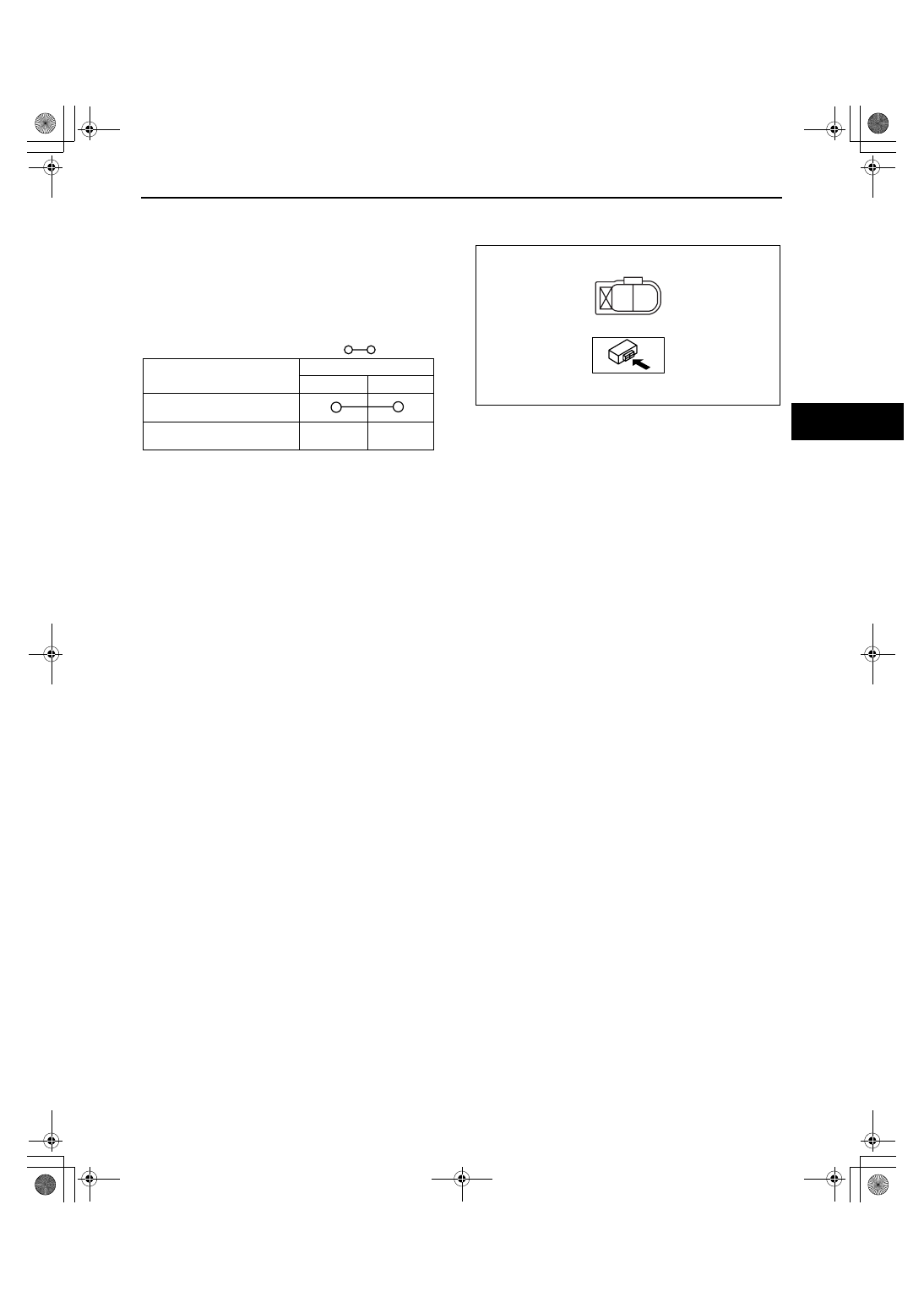
1. Disconnect the brake fluid level sensor connector from the master cylinder.
2. Inspect for continuity according to fluid level 

between the brake fluid level sensor terminals.

• If not as indicated in the table, replace the 

No.1 reserve tank. (See 04-11-10 MASTER 
CYLINDER REMOVAL/INSTALLATION.)

End Of Sie

WM: POWER BRAKE UNIT

POWER BRAKE UNIT INSPECTION

id041100801700

Note

• The following inspection methods are simple inspection methods to judge the function of the power brake 

unit.

• If there is any malfunction in the power brake unit, replace the power brake unit as a single unit.

Without Using SST
Operation inspection

1. With the engine stopped, pump the pedal a few times.
2. With the pedal depressed, start the engine.
3. If the pedal moves down slightly immediately after starting the engine, the unit is normal.

Vacuum function inspection

1. Start the engine.
2. Stop the engine after driving the vehicle for 1— 2 min.
3. Depress the pedal with normal force.
4. If the first pedal stroke is long and becomes shorter with subsequent strokes, the unit is normal.

• If a problem is found, inspect for damage to or improper installation of the check valve and vacuum hose. 

After repairing, inspect again.

Vacuum loss function inspection

1. Start the engine.
2. Depress the pedal with normal force.
3. With the pedal depressed, stop the engine.
4. Hold the pedal depressed for approx. 30 s.
5. If the pedal height does not change during this time, the unit is normal.

A

B

ampjjw00002672

: Continuity

Condition

Above MIN

Below MIN

Terminal

B

A

acxuuw00001089

1871-1U-06B(04-11).fm  11 ページ  2006年3月15日 水曜日 午前11時13分

CONVENTIONAL BRAKE SYSTEM 

04-11–12

Using SST
Pre-inspection preparation

1. Install the SST (49 N043 001) to the master 

cylinder in the orientation shown in the figure.

Note

• When installing the SST (49 N043 001) to 

the master cylinder, use a commercially 
available flare nut wrench.

— Flare nut across flat: 12 mm {0.47 in}

2. Connect the SSTs, a vacuum gauge, and a pedal 

force gauge to the master cylinder, and bleed the 
air from the SSTs and the brake line. (Bleed the 
air from the SSTs using air bleed valve A.)

Vacuum loss inspection

1. Start the engine.
2. Depress the brake pedal with a force of 200 N {20.4 kgf, 44.9 lbf}.
3. Stop the engine when the vacuum gauge reading reaches 68 kPa {510 mmHg, 20.1 inHg} with the pedal 

depressed.

4. With the engine off, observe the vacuum gauge for 15 s.
5. If the gauge has dropped 3.3 kPa {25 mmHg, 1.0 inHg} or less, the unit is normal.

Lack of hydraulic pressure inspection

1. If the pedal force and fluid pressure correlation is within the specification with the engine stopped and a vacuum 

amount of 0 kPa {0 mmHg, 0 inHg}, the system is normal.

Master cylinder fluid pressure

Hydraulic pressure inspection

1. Start the engine. Depress the brake pedal when the vacuum reaches 66.7 kPa {500 mmHg, 19.7 inHg}.
2. At this time, apply the indicated pedal force and if the fluid pressure is within the specification, the unit is 

normal.

Master cylinder fluid pressure

End Of Sie

49 N043 001

TO SST

TO MASTER 
CYLINDER

FLARE NUT ACROSS FLAT 
12 mm {0.47 in}

acxuuw00001746

49 U043 005

49 N043 001

49 U043 006

49 U043 004A

PEDAL FORCE 
GAUGE

VACUUM
GAUGE

A

acxuuw00001863

Vacuum amount at o kPa {0 mmHg, 0 inHg}

Pedal force (N {kgf, lbf}) 

Fluid pressure (kPa {kgf/cm2, psi}) 

200 N {20.4kgf, 44.9lbt}

550 kPa {5.61 kgf/cm

2

, 79.8 psi} or more

Vacuum amount at 66.7 kPa {500 mmHg, 19.7 inHg}

Pedal force (N {kgf, lbf}) 

Fluid pressure (kPa {kgf/cm2, psi}) 

200 N {20.4kgf, 44.9lbt}

6,950 kPa {70.88 kgf/cm

2

, 1.009 psi} or more

1871-1U-06B(04-11).fm  12 ページ  2006年3月15日 水曜日 午前11時13分

CONVENTIONAL BRAKE SYSTEM 

04-11–13

04-11

POWER BRAKE UNIT REMOVAL/INSTALLATION

id041100801800

1. Remove the battery and battery tray. (See 01-17-2 BATTERY REMOVAL/INSTALLATION[L3 WITH TC].)
2. Remove the battery tray bracket as shown in the 

figure.

3. Remove the master cylinder component. (See 04-

11-10 MASTER CYLINDER REMOVAL/
INSTALLATION.)

4. Remove the brake pipe as shown in the figure.
5. Remove the accelerator pedal. (See 01-13-17 

ACCELERATOR PEDAL REMOVAL/
INSTALLATION[L3 WITH TC].)

6. Remove in the order indicated in the table.

BATTERY TRAY BRACKET

18—26 N·m 
{1.9—2.6 kgf·m,
 14—19 ft·lbf}

acxuuw00001901

12.8—21.6 N·m 
{131—220 kgf·cm,
 114—191 in·lbf}

COMMERCIALLY AVAILABLE FLARE NUT WRENCH 
(FLARE NUT ACROSS FLAT 10 mm {0.39 in})

A

*

A

*

acxuuw00001865

1871-1U-06B(04-11).fm  13 ページ  2006年3月15日 水曜日 午前11時13分

CONVENTIONAL BRAKE SYSTEM 

04-11–14

7. Install in the reverse order of removal.
8. After installation, add brake fluid, bleed the air, and inspect for fluid leakage. (See 04-11-3 AIR BLEEDING.)
9. Inspect the brake pedal. (See 04-11-4 BRAKE PEDAL INSPECTION.)

.

End Of Sie

WM: FRONT BRAKE (DISC)

FRONT BRAKE (DISC) INSPECTION

id041100800800

Brake Judder Repair Hint
Description
Brake judder concern has the following three characteristics:

Steering wheel vibration
Steering wheel vibrates in the direction of its rotation. This characteristic is most noticeable when applying brakes 
at a vehicle speed of 100— 140 km/h {62— 87 mph}.

Floor vibration
When applying brakes, the vehicle body shakes back and forth. The seriousness of shake is not influenced by 
vehicle speed.

Brake pedal vibration
When applying brakes, a pulsating force tries to push the brake pad back. The pulsation is transmitted to the brake 
pedal.
The following are the main possible causes of brake judder:

Due to an excessive runout (side-to-side wobble) of disc plate, the thickness of disc plate is uneven.
If the runout is more than 0.05 mm {0.002 in} at the position 10 mm {0.39 in} from the disc plate edge, uneven 
wear occurs on the disc plate because of uneven pad/plate contact.
If the runout is less than 0.05 mm {0.002 in}, uneven wear does not occur.

1

5

2

3

4

A

A

B

B

R

18.6—25.5 N·m 
{1.90—2.60 kgf·m,
 13.8—18.8 ft·lbf}

acxuuw00001091

1

Vacuum hose

2

Snap pin

3

Clevis pin

4

Power brake unit

5

Gasket

1871-1U-06B(04-11).fm  14 ページ  2006年3月15日 水曜日 午前11時13分


Content   ..  208  209  210  211   ..