Mazda 6. Manual - part 177


  Index      Mazda     Mazda 6 - service repair manual 2002 year


Search            


Content   ..  175  176  177  178   ..


Mazda 6. Manual - part 177


F–230

TROUBLESHOOTING 

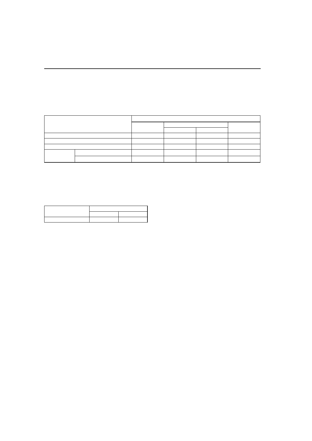
7. Verify that the engine speed is within the specification under each load condition.

• If not as specified specific load condition, inspect the following.

— A/C switch and related harness

(See 

U–47 CLIMATE CONTROL UNIT INSPECTION

.)

— Fan switch and related harness

(See 

U–47 CLIMATE CONTROL UNIT INSPECTION

.)

— PSP switch and related harness

(See 

F–58 POWER STEERING PRESSURE (PSP) SWITCH INSPECTION

.)

Engine speed

*1

: Neutral or P position

*2

: A/C switch and fan switch are on.

*3

: Refrigerant pressure switch (middle pressure) is off.

*4

: Refrigerant pressure switch (middle pressure) is on.

VIS Operation Inspection

1. Start the engine.
2. Inspect the rod operation under the following condition.

Rod operation

• If the rod operation is not as specified, inspect as follows.

(1) Stop the engine.
(2) Connect WDS or equivalent to the DLC-2.
(3) Verify that DTC P0661 or P0662 is not displayed.

• If DTC P0661 or P0662 is shown, carry out DTC inspection.

(See 

F–67 DTC TABLE

.)

(4) Turn ignition switch to ON.
(5) Turn the VIS control solenoid valve from on to off using the IVC PID and verify that operation sound of the 

solenoid valve is heard.

• If the operation sound is heard, inspect the following.

— Vacuum hose and vacuum chamber for looseness or damage
— Shutter valve actuator

(See 

F–14 VARIABLE INTAKE-AIR SYSTEM (VIS) SHUTTER VALVE ACTUATOR INSPECTION 

(L3)

.)

— Shutter valve stuck open or close

• If the operation sound is not heard, inspect the following.

— VIS control solenoid valve

(See 

F–14 VARIABLE INTAKE-AIR SYSTEM (VIS) CONTROL SOLENOID VALVE INSPECTION 

(L3)

.)

Load condition

Engine speed (rpm)

*1

L8

LF

L3

MTX

ATX

No load

650—750

600—700

650—750

600—700

E/L operating

650—750

650—750

650—750

650—750

P/S operating

700—800

650—750

650—750

650—750

A/C operating

*2

Refrigerant pressure low

*3

700—800

700—800

650—750

700—800

Refrigerant pressure high

*4

700—800

700—800

700—800

700—800

Engine speed

 Approx. 4,400 rpm

Below

Above

Shutter valve actuator

Operate

Not operate

TROUBLESHOOTING 

F–231

F

Variable Tumble Control System (VTCS) Operation Inspection

1. Connect the WDS or equivalent to the DLC-2.
2. Access ECT PID.
3. Verify that ECT PID is between 63

°C {145°F} and 67°C {152°F}.

4. Start the engine.
5. Inspect rod operation under the following condition.

Rod operation

• If the rod operation is not specified, inspect as follows.

(1) Verify that DTC No. P2009 or P2010 is not displayed.

• If DTC No. P2009 or P2010 are shown, carry out DTC inspection.

(See 

F–67 DTC TABLE

.)

(2) Turn ignition switch to ON.
(3) Turn the VTCS solenoid valve from on to off using the IMRC PID and verify that operation sound of the 

solenoid valve is heard.

• If the operation sound is heard, inspect the following.

— Vacuum hose and vacuum chamber for looseness or damage
— Shutter valve actuator

(See 

F–15 VARIABLE TUMBLE CONTROL SYSTEM (VTCS) SHUTTER VALVE ACTUATOR 

INSPECTION

.)

— Shutter valve stuck open or close

• If the operation sound is not heard, inspect the following.

— VIS control solenoid valve

(See 

F–15 VARIABLE TUMBLE CONTROL SOLENOID VALVE INSPECTION

.)

Fuel Injector Operation Inspection

Fuel Cut Control System Inspection

1. Warm up engine and let it idle.
2. Turn off the electrical loads and A/C switch.
3. Connect WDS or equivalent to the DLC-2.
4. Select RPM and FUELPW1 PIDs.
5. Monitor both PIDs while performing the following steps.

(1) Depress the accelerator pedal and increase the engine speed to 4,000 rpm.
(2) Release the accelerator pedal (brake pedal is not depressed) and verify that the fuel injector duration time 

is 0 msec., and 2—5 msec. when the engine speed drops below 1,200 rpm.

• If not as specified, inspect the following.

— ECT sensor and related harness

(See 

F–53 ENGINE COOLANT TEMPERATURE (ECT) SENSOR INSPECTION

.)

— Neutral/clutch switch and related harness (MTX)

(See 

F–59 CLUTCH SWITCH INSPECTION

.)

— TR switch and related harness (ATX)

(See 

K–14 TRANSAXLE RANGE (TR) SWITCH INSPECTION

.)

Engine speed

3,750 rpm

Below

Above

Shutter valve actuator

Operate

Not operate

STEP

INSPECTION

RESULTS

ACTION

1

While cranking engine, inspect for fuel injector 
operation sound at each cylinder using a 
soundscope.
Is operation sound heard?

Yes

Fuel injector operation is okay.

No

All cylinders no heard:
Go to next step.
Some cylinders no heard:
Go to Step 3.

2

Carry out main relay operation inspection.
Is main relay operation normal?

Yes

Inspect following:

• Fuel injector power system related wiring harness 

and connectors

• PCM connectors

• Fuel injector GND and related wiring harness and 

connectors

No

Repair or replace malfunctioning parts.

3

Change fuel injector connector of not operating 
fuel injector and operating fuel injector.
Is operation sound heard?

Yes

Go to next step.

No

Replace fuel injector.

4

Are wiring harness and connectors of not 
operation fuel injector okay? (Open or short)

Yes

Inspect PCM terminal voltage of fuel injector signal.

No

Repair or replace malfunctioning parts.

F–232

TROUBLESHOOTING 

Fuel Pump Operation Inspection

1. Connect WDS or equivalent to the DLC-2.
2. Remove the fuel-filler cap.
3. Turn the ignition switch to ON position.
4. Turn the fuel pump relay from off to on using the FP PID and inspect if the operation sound is heard.

• If no operation sounds is heard, proceed to next step.

5. Measure the voltage at harness side fuel pump connector terminal B.

Specification

B+ (Ignition switch is on)

• If the voltage is as specified, inspect the following.

— Fuel pump continuity
— Fuel pump GND
— Wiring harness between fuel pump relay and PCM terminal 4P (without immobilizer system), 4Q (with 

immobilizer system)

• If not as specified, inspect the following.

— Fuel pump relay (See 

T–24 RELAY INSPECTION

.)

— Wiring harness and connector (Main relay-fuel pump relay-fuel pump)

Fuel Pump Control System Inspection

1. Connect WDS or equivalent to the DLC-2.
2. Turn the ignition switch to ON position.
3. Select FP PID.
4. Turn the fuel pump relay from off to on and inspect if the operation sound of the fuel pump relay is heard.

• If no operation sound is heard, inspect the fuel pump relay.

• If the fuel pump relay is normal, inspect the following.

— Wiring harnesses and connectors (Main relay-fuel pump relay-PCM)

Spark Test

1. Remove the fuel pump relay.
2. Verify that each high-tension lead and connector is connected properly.
3. Inspect the ignition system in the following procedure.

Warning

• High voltage in the ignition system can cause strong electrical shock which can result in serious 

injury. Avoid direct contact to the vehicle body during the following spark test.

STEP

INSPECTION

RESULTS

ACTION

1

Note

• No.1 and No.4 cylinders and No.2 and 

No.3 cylinders are ignited simultaneously.

Disconnect high-tension lead from spark plugs.
Remove spark plugs.
Reconnect spark plugs to high-tension lead.
Ground spark plugs to engine.
Is strong blue spark visible at each cylinder while 
cranking?

Yes

Ignition system is okay.

No

Some cylinders do not spark:
Go to next step.
All cylinders do not spark:
Go to Step 5.

2

Inspect spark plugs for damage, wear, carbon 
deposits and proper plug gap.
Are spark plugs okay?

Yes

Go to next step.

No

Replace spark plugs, then go to Step 1.

3

Inspect high-tension leads for insulation 
damage, looseness, shorting or other damage.
Are high-tension leads okay?

Yes

Go to next step.

No

Replace high-tension leads, then go to Step 1.

4

Inspect following wiring harnesses for open or 
short:

• Ignition coil terminal C-PCM terminal 1A

• Ignition coil terminal A-PCM terminal 1B

Are wiring harnesses okay?

Yes

Inspect and replace ignition coil.
See 

G–9 IGNITION COIL INSPECTION

.

No

Repair or replace malfunctioning parts, then go to Step 
1.

5

Measure voltage at terminal B in ignition coil.
Is voltage reading B+?

Yes

Go to next step.

No

Inspect power supply circuit of ignition coil.

6

Does PCM connector or ignition coil connector 
have poor connection?

Yes

Repair or replace connector, then go to Step 1.

No

Go to next step.

TROUBLESHOOTING 

F–233

F

EGR Control System Inspection

1. Verify that EGR valve operation (initial operation) sound is heard when the ignition switch is turned to ON 

position.

• If the operation sound is not heard, connect WDS or equivalent to the DLC-2 and verify that the DTC P0403 

is shown. Carry out DTC inspection. (See 

F–67 DTC TABLE

.)

2. Start the engine and run it at idle.
3. Increase the step value of EGR valve from 0 to 40 using SEGRP PID.
4. Operate the EGR valve and inspect if the engine speed becomes unstable or the engine stalls.

• If the engine speed will not change, proceed to following.

(1) Stop the engine.
(2) Remove the EGR valve.
(3) Connect the EGR valve connector.
(4) Turn the ignition switch to ON.
(5) Increase the step value of EGR valve from 0 to 40 using SEGRP PID.
(6) Inspect the EGR operation.

• If the EGR valve is operated, clean the EGR valve and reinspect from Step 2.

• If the EGR valve will not operate, replace the EGR valve and reinspect from Step 2.

5. Warm up the engine to normal operating temperature.
6. Select the following PIDs.

• ECT

• RPM

• SEGRP

• TP

• VSS

7. Let the vehicle idle and verify that the SEGRP value is 0.
8. Put the vehicle in drive.
9. Depress the accelerator pedal and verify that the SEGRP value is increased.

• If the SEGRP value will not increase, inspect the VSS, TP and ECT PIDs. (See 

F–45 PCM INSPECTION

.)

10. Stop the vehicle and verify that the SEGRP value is returned 0.

Purge Control System Inspection

1. Start the engine.
2. Disconnect the vacuum hose between the purge solenoid valve and the charcoal canister.
3. Put a finger to the purge solenoid valve and verify that there is no vacuum applied when the engine is cold.

• If there is a vacuum, inspect the following.

— Wiring harness and connectors (Purge solenoid valve-PCM terminal 4U)
— Purge solenoid valve

4. Warm up the engine to the normal operating temperature.
5. Stop the engine.
6. Connect WDS or equivalent to the DLC-2 and verify that the DTC P0443 is shown. Carry out DTC inspection. 

(See 

F–67 DTC TABLE

.)

7. Turn the ignition switch to ON position.
8. Select ECT PID.
9. Verify that the engine coolant temperature is above 60

°C {140°F}.

• If WDS or equivalent indicates below 60°C {140°F}, carry out the ECT sensor inspection.

10. Select EVAPCP PID.
11. Increase the duty value of the purge solenoid valve to 50% and inspect if the operation sound of the valve is 

heard.

• If the operation sound is heard, inspect for the loose or damaged vacuum hose. (Intake manifold-purge 

solenoid valve-charcoal canister)

• If the operation sound is not heard, carry out the purge solenoid valve inspection.

7

Are following item okay?

• CKP sensor and crankshaft pulley

• PCM terminal 1A/1B voltage

Specification

Approx. 1.5 V

Yes

Inspect for open or short in wiring harness and 
connector of CKP sensor.

No

Repair or replace malfunctioning parts, then go to Step 
1.

STEP

INSPECTION

RESULTS

ACTION


Content   ..  175  176  177  178   ..