Mazda Protege 5. Manual - part 354
INSTRUMENTATION/DRIVER INFO.
09–22–10
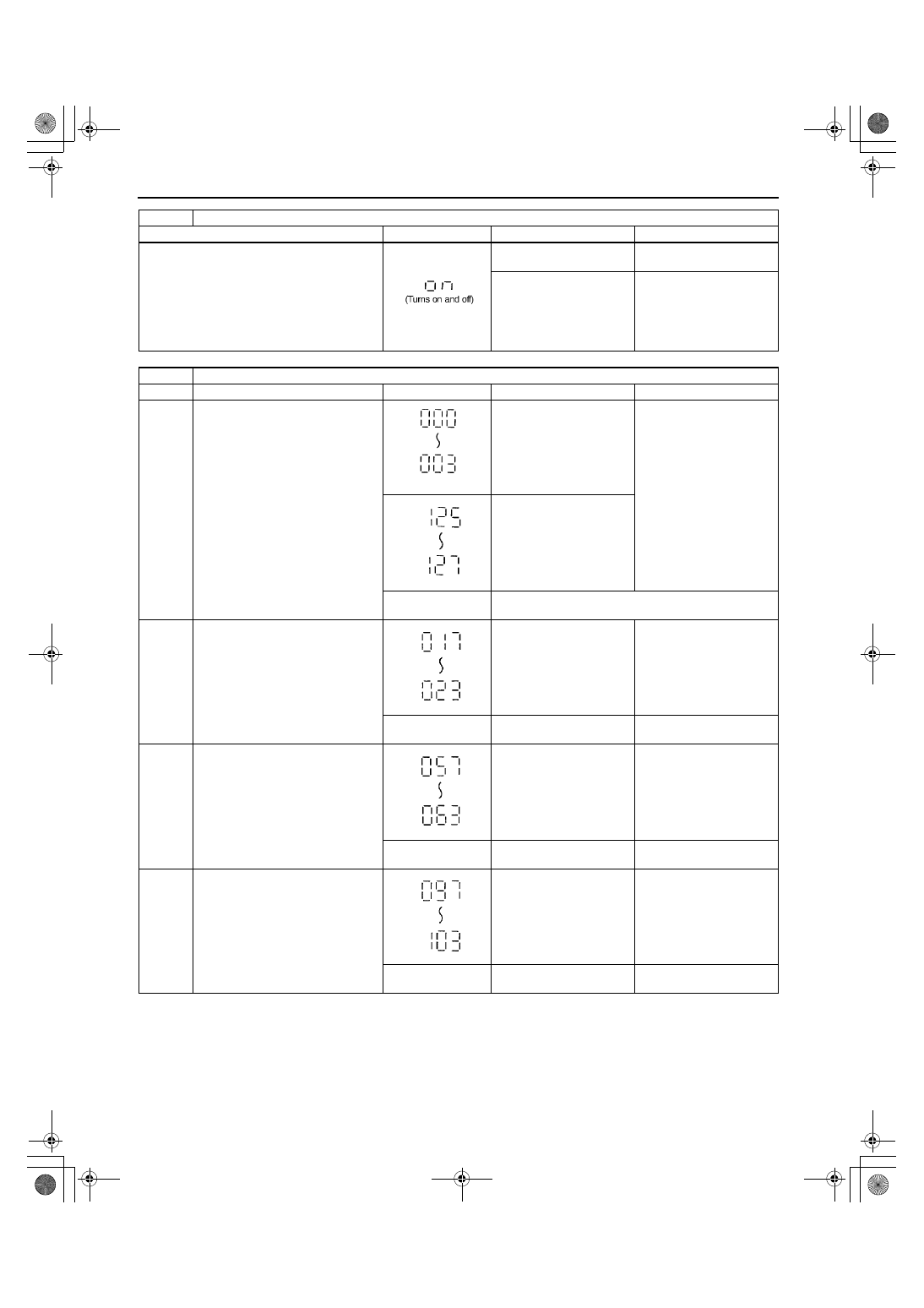
DTC 16
Operation signal to fuel-level warning light
INSPECTION
INDICATION
SITUATION
ACTION
Wait for 2 seconds after selecting DTC 16.
Fuel-level warning light
turns on and off 3 times.
Fuel-level warning light is
okay.
Other than stated above.
Inspect fuel-level warning
light.
(See 09–22–13 WARNING
AND INDICATOR LIGHT
BULB REMOVAL/
INSTALLATION)
DTC 22
Fuel level signal
STEP
INSPECTION
INDICATION
SITUATION
ACTION
1
Select DTC 22.
Short to GND.
•
Inspect fuel gauge
sender unit.
(See 09–22–13 FUEL
GAUGE SENDER
UNIT INSPECTION)
•
Inspect wiring harness.
(Instrument cluster —
fuel gauge sender
unit.)
Open circuit.
Other than stated
above.
Go to next step.
2
Using SST (Fuel And Thermometer
checker), input 20 ohms to terminal
3C of instrument cluster.
—
Go to next step.
Other than stated
above.
—
Replace instrument
cluster.
3
Using SST (Fuel And Thermometer
checker), input 60 ohms to terminal
3C of instrument cluster.
—
Go to next step.
Other than stated
above.
—
Replace instrument
cluster.
4
Using SST (Fuel And Thermometer
checker), input 100 ohms to
terminal 3C of instrument cluster.
—
Input signal to instrument
cluster is okay.
Other than stated
above.
—
Replace instrument
cluster.
1712-1U-01G(09-22).fm 10 ページ 2001年6月29日 金曜日 午前10時39分