Mazda Protege 5. Manual - part 353
INSTRUMENTATION/DRIVER INFO.
09–22–6
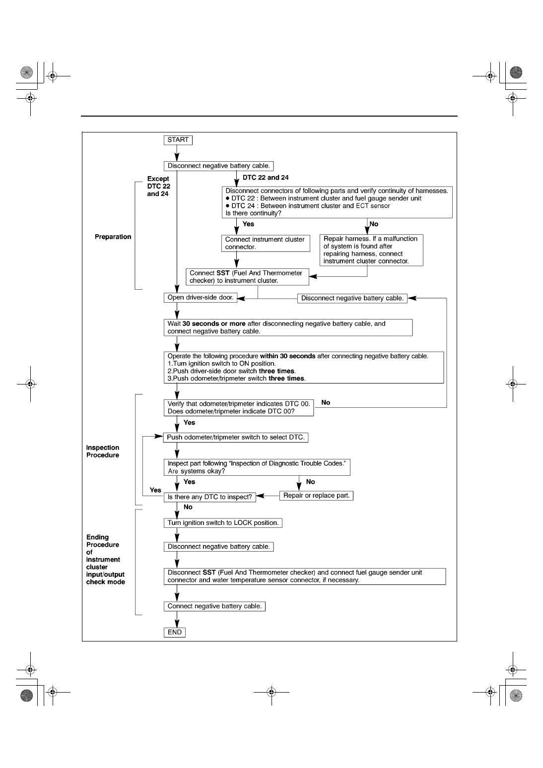
Operating Order
Z3U0922W002
1712-1U-01G(09-22).fm 6 ページ 2001年6月29日 金曜日 午前10時39分
|
|
|
INSTRUMENTATION/DRIVER INFO. 09–22–6 Operating Order Z3U0922W002 1712-1U-01G(09-22).fm 6 ページ 2001年6月29日 金曜日 午前10時39分 |