Mazda Protege 5. Manual - part 114
SYMPTOM TROUBLESHOOTING [ENGINE CONTROL SYSTEM (FS)]
01–03B–49
01–03B
End Of Sie
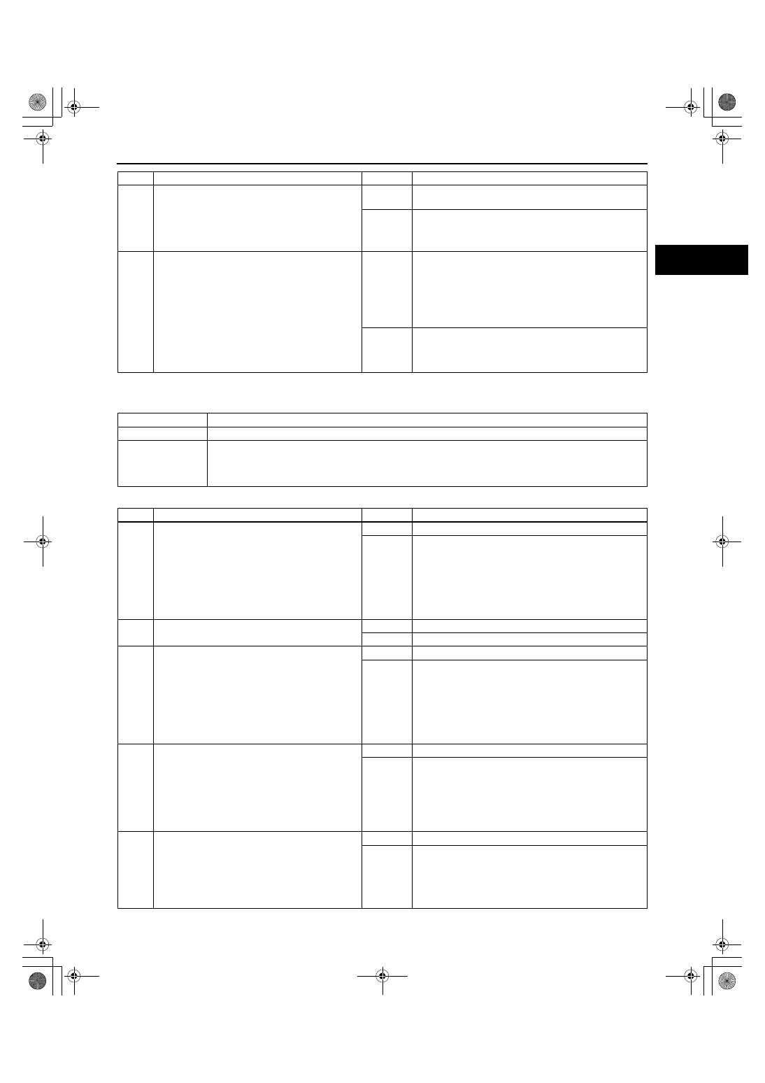
NO.30 REFERENCE VOLTAGE [FS]
A3U010318881W35
Diagnostic procedure
3
•
Start engine.
•
Lightly tap on suspect component, wiggle
and pull each wire/connector at suspect
component or PCM.
•
Are any PID values out of range, or do they
suddenly change and go back into range?
Yes
Inspect each wire for corrosion, bent or loose terminal
crimps.
No
Go to next step.
4
•
Start engine.
•
Accurately spray water on suspect
component wire, component or vacuum line
related to possible fault area.
•
Are any PID values out of range, or suddenly
change and go back into range, or was there
a noticeable engine misfire/stumble?
Yes
Fault occurred while spraying on component:
•
Replace part and verify repair.
Fault occurred while spraying wiring:
•
Inspect each wire for corrosion, bent or loose
terminals and poor wire terminal crimps.
Fault occurred while spraying vacuum line:
•
Repair vacuum hoses.
No
Inspect wire and connector at suspect component for
corrosion, bent or loose terminals, poor wire terminal
crimps and high tension of wire.
Repair as necessary.
STEP
INSPECTION
RESULTS
ACTION
30
Reference voltage
DESCRIPTION
•
Incorrect reference voltage
POSSIBLE CAUSE
•
Reference voltage circuit malfunction
Note
•
TP sensor, EGR boost sensor and fuel tank pressure sensor use reference voltage.
STEP
INSPECTION
RESULTS
ACTION
1
•
Disconnect appropriate sensor connector
when reference voltage circuit inspection
failed.
•
Turn ignition key to ON.
•
Measure voltage between following
appropriate sensor connector terminals:
— Reference voltage terminal — GND
terminal
•
Is reference voltage greater than 6.0 V?
Yes
Go to Step 13.
No
Go to next step.
2
•
Is voltage across battery terminals greater
than 10.5 V?
Yes
Go to next step.
No
Inspect charging system.
3
•
Turn ignition key to LOCK.
•
Leave appropriate sensor connector
disconnected.
•
Measure voltage between battery positive
terminal and GND (between PCM and
appropriate sensor) circuit at appropriate
sensor connector.
•
Is voltage greater than 10.5 V and within
1.0 V of battery voltage?
Yes
Go to next step.
No
Go to Step 8.
4
Note
•
The purpose of this step is to determine if
WDS or equivalent is communicating with
PCM.
•
Turn ignition key to ON.
•
Attempt to access ECT PID.
•
Can ECT PID be accessed?
Yes
Go to Step 7.
No
Go to next step.
5
•
Turn ignition key to LOCK.
•
Disconnect TP sensor, EGR boost sensor,
FTP sensor and PCM connectors.
•
Turn ignition key to ON.
•
Measure voltage between PCM connector
terminals 71/97 and 24/51/76/77/103.
•
Is voltage greater than 10.5 V?
Yes
Go to next step.
No
Repair open circuit between PCM terminal 71/97 and
main relay.
1712-1U-01G(01-03B).fm 49 ページ 2001年6月29日 金曜日 午前9時33分