Mazda Protege 5. Manual - part 115
SYMPTOM TROUBLESHOOTING [ENGINE CONTROL SYSTEM (FS)]
01–03B–53
01–03B
End Of Sie
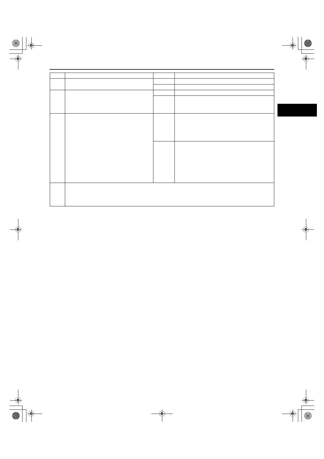
14
•
Carry out compression inspection.
•
Is compression correct?
Yes
Inspect for clogging in exhaust system.
No
Repair or replace malfunctioning part.
15
•
When engine cannot be started, inspect
intake-air system for air leakage.
•
When engine can be started, carry out intake
manifold vacuum inspection.
•
Is air sucked in from intake-air system?
Yes
Repair or replace malfunctioning part.
No
Go to next step.
16
•
Carry out fuel line pressure inspection.
•
Is fuel line pressure correct?
Fuel line pressure
260—310 kPa {2.6—3.2 kgf/cm
2
, 37—45 psi}
Yes
Inspect following PIDs.
•
ECT
•
O2S11
•
O2S12
•
MAF
Inspect PCM GND condition.
No
Zero or low:
•
Inspect fuel pump circuit.
•
Inspect open for fuel pump relief valve.
•
Inspect for fuel leakage inside pressure regulator.
•
Inspect for clogged main fuel line.
•
Inspect pulsation damper.
High:
•
Inspect pressure regulator for high pressure cause.
•
Inspect for clogged fuel return line.
17
•
Verify test results.
— If okay, return to diagnostic index to service any additional symptoms.
— If malfunction remains, inspect related Service Bulletins and perform repair or diagnosis.
•
If vehicle is repaired, troubleshooting is completed.
•
If vehicle is not repaired or additional diagnostic information is not available, replace PCM.
STEP
INSPECTION
RESULTS
ACTION
1712-1U-01G(01-03B).fm 53 ページ 2001年6月29日 金曜日 午前9時33分