Mazda Protege 5. Manual - part 31
ON-BOARD DIAGNOSTIC [ENGINE CONTROL SYSTEM (ZM)]
01–02A–90
DTC P0463 [ZM]
A3U010201086W27
Diagnostic procedure
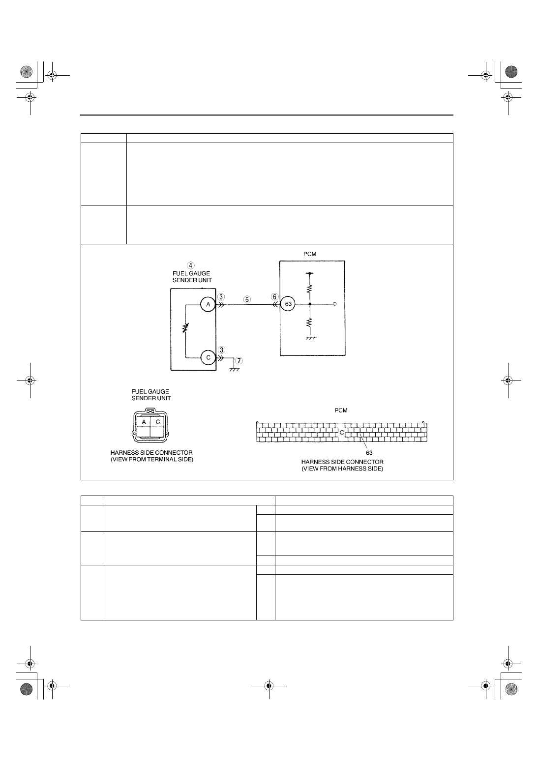
DTC P0463
Fuel gauge sender unit circuit high input
DETECTION
CONDITION
•
PCM monitors the voltage of fuel gauge sender unit. If PCM detects PCM terminal 63 voltage above 4.92
V for 5 seconds, PCM determines that fuel gauge sender unit circuit has a malfunction.
Diagnostic support note
•
This is a continuous monitor (CCM).
•
MIL illuminates if PCM detects the above malfunction condition in two consecutive drive cycles.
•
PENDING CODE is available if PCM detects the above malfunction condition during first drive cycle.
•
FREEZE FRAME DATA is available.
•
DTC is stored in PCM memory.
POSSIBLE
CAUSE
•
Fuel gauge sender unit malfunction
•
Open circuit between fuel gauge sender unit terminal A and PCM terminal 63.
•
Open circuit between fuel gauge sender unit terminal C and body ground.
•
Poor connection of fuel gauge sender unit and/or PCM connector
•
PCM malfunction
STEP
INSPECTION
ACTION
1
VERIFY FREEZE FRAME DATA HAS BEEN
RECORDED
•
Has FREEZE FRAME DATA been recorded?
Yes Go to next step.
No
Record FREEZE FRAME DATA on repair order, then go to
next step.
2
VERIFY RELATED REPAIR INFORMATION
AVAILABILITY
•
Check for related Service Bulletins availability.
•
Is any related repair information available?
Yes Perform repair or diagnosis according to available repair
information.
•
If vehicle is not repaired, go to next step.
No
Go to next step.
3
INSPECT FUEL GAUGE SENDER UNIT
CONNECTOR FOR POOR CONNECTION
•
Turn ignition key to OFF.
•
Disconnect fuel gauge sender unit connector.
•
Check for poor connection (damaged/pulled-
out terminals, corrosion, etc.).
•
Is there malfunction?
Yes Repair suspected terminal, then go to Step 8.
No
Go to next step.
1712-1U-01G(01-02A).fm 90 ページ 2001年6月29日 金曜日 午後2時20分