Mazda 5. Manual - part 74


  Index      Mazda     Mazda 5 - service repair manual


Search            


Content   ..  72  73  74  75   ..


Mazda 5. Manual - part 74


BODY STRUCTURE [PANEL REPLACEMENT]

09–80B–59

09

End Of Sie

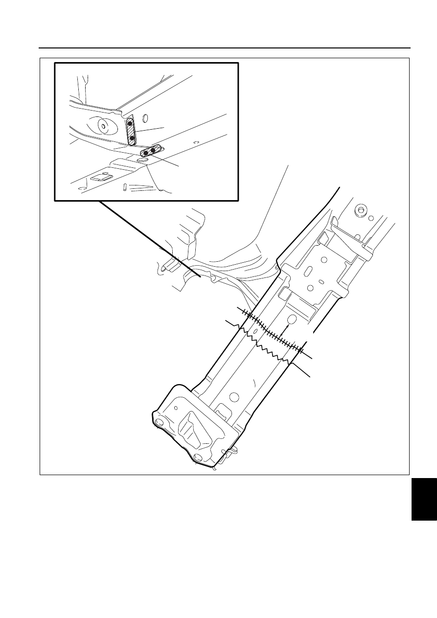
REAR SIDE FRAME (PARTIAL CUTTING) INSTALLATION

DPE098053810B02

Caution

• The cut-and-joint area indicates the maximum size range of the installation position.

1. Make a reinforcement panel using the material from the rear side frame.
2. To cut and join the new and existing parts, cut the new part at the specified location shown in the figure, and 

chamfer the joint surfaces of the new and existing parts.

3. When installing the new parts, trial-fit new and existing parts, and then measure and adjust the body to conform 

with standard dimensions.

4. After temporarily installing new parts, make sure the related parts fit properly.

30mm

{1.18in}

2

2

ROUGH CUT LOCATION

CUT-AND-JOIN LOCATION

DPE0980B120

09–80B–60

BODY STRUCTURE [PANEL REPLACEMENT]

5. Trial-fit the new and existing parts, weld the existing parts and the reinforcement, and then butt weld the new 

and existing parts.

Caution

• Press fit the reinforcement panel and the body side material, and then plug weld them.

End Of Sie

ROOF PANEL REMOVAL

DPE098070600B01

1. Drill the 81 locations indicated by (A).
2. The side frame (outer) and the roof panel are joined with weld bond at area (B). Use a chisel or similar tool to 

separate them, then remove the roof panel.

Caution

• Only the procedure for the right side is described, however, the procedure for the left side is the 

same.

3. Remove the weld bond using a disc grinder.

50mm

20mm

t=1.8mm

L=10mm x 2

L=10mm x 4

30mm

{1.18in}

{0.39in}

{0.39in}

REINFORCEMENT

NEW REAR SIDE FRAME

{0.79in}

{1.97in}

{0.07in}

2

2

CUT-AND-JOIN LOCATION

DPE0980B121

BODY STRUCTURE [PANEL REPLACEMENT]

09–80B–61

09

End Of Sie

ROOF PANEL INSTALLATION

DPE098070600B02

1. When installing new parts, measure and adjust the body as necessary to conform with standard dimensions.
2. Drill holes for plug welds before installing new parts.

Caution

• Area (A) was joined with the weld bond. When installing the roof panel, plug weld the 4 locations 

indicated by (B).

• Only the procedure for the right side is described, however, the procedure for the left side is the 

same.

3. After temporarily installing new parts, make sure the related parts fit properly.

(A)27

(B)

(A)27

(A)19

(A)8

400mm {15.75in}

WELD BOND APPLICATION AREA

30—50mm

{1.18—1.97in}

110—130mm

{4.33—5.12in}

DPE0980B114

09–80B–62

BODY STRUCTURE [PANEL REPLACEMENT]

End Of Sie

17

6

8

(B)1

3

(B)2

1

(B)1

6

8

19

8

17

(A)400mm

30—50mm

110—130mm

{1.18—1.97in}

{15.75in}

{4.33—5.12in}

DPE0980B115


Content   ..  72  73  74  75   ..