Mazda X-5. Manual - part 41
CONTROL SYSTEM
01–40–37
01–40
GENERATOR CONTROL OUTLINE [LF]
E5U014000000N52
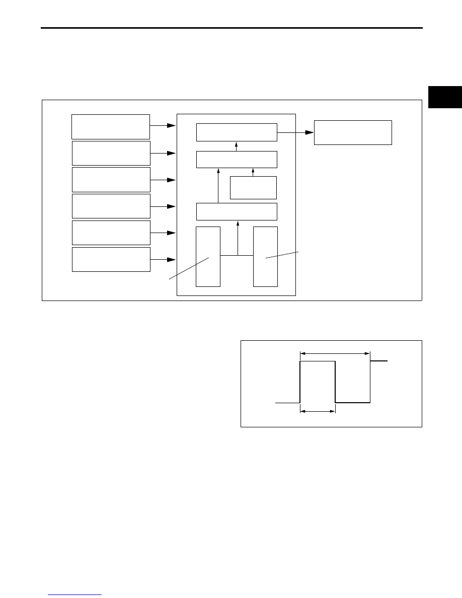
• Idling stability and the corresponding load performance have been improved by optimum control of generator
voltage according to engine operation and electrical load conditions.
• The PCM determines the engine operation and electrical load conditions based on the input signals from input
devices shown in the figure below and controls the excitation time of the generator field coils.
End Of Sie
GENERATOR CONTROL BLOCK DIAGRAM [LF]
E5U014000000N53
End Of Sie
GENERATOR CONTROL OPERATION [LF]
E5U014000000N54
Determination of Field Coil Excitation Time
• By sending a duty signal to the power transistor
built into the generator, the PCM increases and
decreases the field coil excitation current.
• The field coil excitation current changes
according to changes in the power transistor
excitation time by changing the duty signal duty
ratio. For example, when the battery voltage is
low, the duty signal duty ratio sent to power
transistor is higher, and the excitation current to
the field coils increases.
Control
• To maintain optimum battery voltage, the PCM calculates the target excitation current based on the targeted
generator current (target generated current) and the generator rotation speed at the time.
• The generator rotation speed is calculated from the generator pulley and crankshaft pulley ratios, and the
engine speed.
• The PCM compares the target battery voltage (regulating voltage) calculated from the intake airflow
temperature, engine speed and vehicle speed with the current battery voltage and, based on this difference,
calculates the required generator current.
• When an electrical load is applied, the target rotation speed increases during idling because the battery voltage
decreases due to the increased power consumption.
End Of Sie
PCM
IAT SENSOR
ECT SENSOR
CKP SENSOR
VEHICLE SPEED SIGNAL
GENERATOR (TERMINAL
P: STATOR COIL)
BATTERY
FIELD COIL EXCITATION
TIME
TARGET EXCITATION
CURRENT
GENERATOR
ROTATION
SPEED
TARGET GENERATED
CURRENT
TARGET BATTERY VOLTAGE
(REGULATING VOLTAGE)
DEVIATION
CURRENT BATTERY
VOLTAGE
GENERATOR (TERMINAL
D: FIELD COIL)
E5U140ZT5011
1 CYCLE
EXCITATION TIME
C3U0140S029