Mazda X-5. Manual - part 39


  Index      Mazda     Mazda X-5 - service repair manual 2006 year


Search            


Content   ..  37  38  39  40   ..


Mazda X-5. Manual - part 39


CONTROL SYSTEM 

01–40–29

01–40

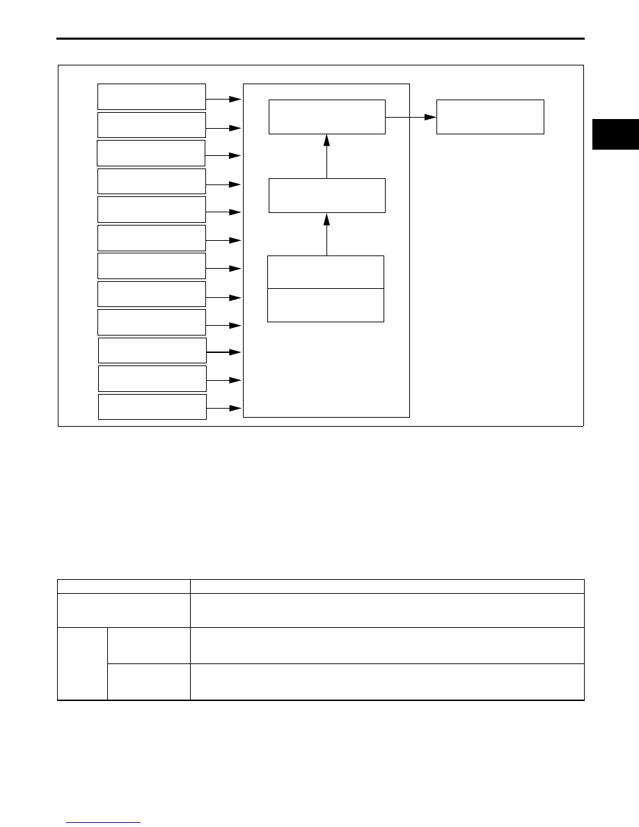
EVAPORATIVE PURGE CONTROL BLOCK DIAGRAM [LF]

E5U014000000N38

End Of Sie

EVAPORATIVE PURGE CONTROL OPERATION [LF]

E5U014000000N39

Determination of Purge Solenoid Valve Energization Time

• The PCM determines the target purge flow amount according to engine operation conditions as the basic flow 

amount. The actual operation delays the build-up of operation current from coil inductance and corrects 
energization time according to fluctuation in battery voltage to cause operation delay based on the mass of the 
needle valve and plunger, and spring resistance. The lower the rate of battery positive voltage, the longer the 
energization time.

Calculation Method for Purge Flow Amount

• The PCM determines the purge flow amount through the addition of each correction to the basic purge flow 

amount.

Operation Conditions

• For purge control during normal driving, the PCM sends a duty signal to the purge solenoid valve when all of 

the following conditions are met.

— Fuel injection control is in the feedback zone or the high load volume increase zone.

— Airflow passage damage related DTC is not stored.

— Engine coolant temperature is 70 

°C {158 °F} or more.

End Of Sie

MAF SENSOR

IAT SENSOR

MAP SENSOR

CKP SENSOR

BARO SENSOR

FRONT HO2S

BATTERY

NEUTRAL SWITCH (MT)

TR SWITCH (AT)

PURGE SOLENOID VALVE 
ENERGIZATION TIME

PURGE FLOW AMOUNT

BASIC PURGE FLOW 
AMOUNT

CORRECTIONS

PURGE SOLENOID 
VALVE

PCM

TP SENSOR NO.1, NO.2

ECT SENSOR

BRAKE SWITCH 

NO.1, NO.2

E5U140ZT5007

Contents

Calculation or determination method of purge flow amount and correction

Basic purge flow amount

The basic purge flow amount is determined by multiplying the intake air temperature 
correction to the purge mass volume which is calculated by multiplying the base purge rate 
and the intake air mass volume, which differs according to engine conditions.

Correction

Purge startup 

correction

Purpose: Prevents a sudden change in air/fuel ratio during the startup of purge control.

During purge control startup

• When purge control operation conditions are met→correction

Volume decrease 

correction

Purpose: Decreases the amount of purge flow and stabilize the air/fuel ratio.

When the fuel injection control feedback correction value is unstable

• According to the front HO2S feedback condition

CONTROL SYSTEM 

01–40–30

EGR CONTROL OUTLINE [LF]

E5U014000000N34

• Adjusts the EGR valve to the optimum opening angle according to engine operation conditions.

• The valve in the EGR valve allows for more precise control by being driven by the stepping motor.

End Of Sie

EGR CONTROL BLOCK DIAGRAM [LF]

E5U014000000N35

End Of Sie

EGR CONTROL OPERATION [LF]

E5U014000000N36

Stepping Motor Operation Principles

• The PCM opens/closes the EGR valve by controlling the amount of stepping motor rotation (step number).

• The stepping motor operates by the combination of coils No.1—4, according to the stepping motor step 

number.

Energization condition for each coil

ON: Energization, OFF: Non-energization

Example of energization condition for each coil and step number

ON: Energization, OFF Non-energization

• The energization condition of stepping motor coils No.1—4 can be verified by verifying the step number from 

“SEGRP” on the PID/data monitor function of the WDS.

MAF SENSOR

IAT SENSOR

ECT SENSOR

PCM

CKP SENSOR

NEUTRAL SWITCH (MT)

CPP SWITCH (MT)

BATTERY

VEHICLE SPEED SIGNAL

EGR VALVE OPERATION 
STEP NUMBER

TARGET EGR 
VALVE 
POSITION

CURRENT 
EGR VALVE 
POSITION

BASIC EGR VALVE 
POSITION

CORRECTIONS

EGR VALVE

TR SWITCH (AT)

TP SENSOR NO.1, NO.2

MAP SENSOR

BARO SENSOR

E5U140ZT5006

When current step number divided 
by eight

0

1

2

3

4

5

6

7

Coil No.1

ON

ON

ON

OFF

OFF

OFF

OFF

OFF

Coil No.2

OFF

OFF

OFF

OFF

ON

ON

ON

OFF

Coil No.3

OFF

OFF

ON

ON

ON

OFF

OFF

OFF

Coil No.4

ON

OFF

OFF

OFF

OFF

OFF

ON

ON

Step  number

0

1

2

3

4

5

6

7

8

9

10

30

52

Coil No.1

ON

ON

ON

OFF

OFF

OFF

OFF

OFF

ON

ON

ON

OFF

OFF

Coil No.2

OFF

OFF

OFF

OFF

ON

ON

ON

OFF

OFF

OFF

OFF

ON

ON

Coil No.3

OFF

OFF

ON

ON

ON

OFF

OFF

OFF

OFF

OFF

ON

OFF

ON

Coil No.4

ON

OFF

OFF

OFF

OFF

OFF

ON

ON

ON

OFF

OFF

ON

OFF

CONTROL SYSTEM 

01–40–31

01–40

Control Outline

• The PCM constantly calculates the optimum target EGR valve position according to the engine operation 

conditions and controls the EGR stepping motor step number so that the current EGR valve position is close to 
the target.

• If the current EGR valve position is smaller than the target EGR position (deviation is a positive number), the 

PCM increases the stepping motor step number and opens the EGR valve. If larger (deviation is a negative 
number), the PCM decreases the stepping motor step number and closes the EGR valve. Step numbers are 
increased or decreased by one step at a time.

Target EGR Valve Position

• The PCM determines the value to increase or decrease the EGR valve opening angle according to the engine 

operation conditions. The PCM determines the target EGR valve position through each correction based on the 
basic EGR valve position that is set according to the engine speed and load.

Target EGR valve position determination table

*1

: The charging efficiency is the ratio of the actual amount of intake air to the maximum air charging amount 

(mass volume) of the cylinder. This value increases proportionately to the increase in engine load.

*2

: The correction is to restrict the basic EGR valve position value. Except for the above conditions and inhibition 

conditions, the correction value is 100%, and the target EGR valve position equals the EGR valve position 
value.

Inhibition Conditions

• To improve driveability and ensure exhaust emission performance, the EGR valve closes when any of the 

following conditions are met.

— When throttle valve is fully closed

— When vehicle is stopped

— When the fuel injection control is in the high volume increase zone

— The engine coolant temperature is 50 

°C {122 °F} or less

— During deceleration

— Engine speed is less than 1,200 rpm or more than 4,200 rpm

— Charging efficiency is less than 12.5% or more than 75%

— During traction control

End Of Sie

Contents

Method for calculating or determining the EGR valve position and correction

Basic EGR valve position

Within steps 0—52 in the stepping motor determined as follows:

• When the engine speed is 1,200—4,200 rpm and the charging efficiency

*1

 is within 

12.5—75%, the engine speed and charging efficiency are determined to be at basic 
position

• When the EGR control inhibition conditions are met, step 0

Correction 

*2

Engine coolant 

temperature 

correction

Purpose: Improved driveability

Engine coolant temperature is 50—55 

°C {122—131 °F}

• The step number is restricted between 0—50% of the basic EGR valve position (low 

engine coolant temperature—low step number) according to the engine coolant 
temperature.

Engine coolant temperature is 55—65 

°C {131—149 °F}

• The step number is restricted between 50—100% of the basic EGR valve position (low 

engine coolant temperature

→low step number) according to the engine coolant 

temperature.

Intake air 

temperature 

correction

Purpose: Improved driveability

Intake air temperature is 50 

°C {122 °F} or less

• Step number is restricted to 100% of the basic EGR valve position (basic EGR valve 

position = step number)

Intake air temperature is 50 

°C {122 °F} or more

• Step number is restricted between 40—100% of basic EGR valve position (low intake 

air temperature

→large step number)

Acceleration/

deceleration 

correction

Purpose: Improved driveability

During acceleration/deceleration, when the throttle valve opening angle 

fluctuation rate is the set value or more

• During acceleration→step number is restricted to 20% of basic EGR valve position

• During deceleration→step number is restricted to 0% of basic EGR valve position

CONTROL SYSTEM 

01–40–32

HEATED OXYGEN SENSOR (HO2S) HEATER CONTROL OUTLINE [LF]

E5U014000000N40

• Stabilized oxygen concentrations, even when the exhaust gas temperature is low, are detected by controlling of 

the HO2S, enabling feedback control of the fuel injection control even during cold-engine starting, improving 
emission performance when cold.

• When the exhaust gas temperature is high, the HO2S is protected from sharp rises in its temperature by 

stopping energization to the HO2S heater.

• Emission performance improvement and protection of the HO2S have both been achieved by the duty control 

of the front and rear HO2S according to the engine operation conditions (exhaust gas temperature).

End Of Sie

HEATED OXYGEN SENSOR (HO2S) HEATER CONTROL BLOCK DIAGRAM [LF]

E5U014000000N41

End Of Sie

HEATED OXYGEN SENSOR (HO2S) HEATER CONTROL OPERATION [LF]

E5U014000000N42

Operation Conditions

• The PCM operates the HO2S when the following conditions are met.

End Of Sie

PCM

ECT SENSOR

IAT SENSOR

CKP SENSOR

TP SENSOR NO.1, NO.2

MAF SENSOR

MAP SENSOR

BARO SENSOR

REAR HO2S HEATER

FRONT HO2S HEATER

BATTERY

E5U140ZW5402

HO2S

Activation condition

Drive signal

Front

• After engine start

• After the engine has started and a fixed period 

of time has elapsed (the elapsed time period 
after the engine starts is determined by ECT).

• ECT is –10 °C {14 °F} or more.

• Battery positive voltage is 9 V or more and less 

than 16 V.

• MAF sensor is normal (no DTC is stored in 

PCM).

• The PCM outputs a duty signal.

• The element temperature is measured by the 

impedance of the HO2S and a duty ratio is 
determined.

Rear

• Starter is off

• After engine start

• After the engine has started and a fixed period 

of time has elapsed (the time period after the 
engine starts lengthen if the ECT falls below 
0

°C {32°F}.

• ECT is –10 °C {14 °F} or more.

• Battery positive voltage is 9 V or more and less 

than 16 V.

• Charging efficiency is the fixed value or less, or 

during fuel cut.

• The PCM outputs a duty signal.


Content   ..  37  38  39  40   ..