Mazda X-5. Manual - part 29


  Index      Mazda     Mazda X-5 - service repair manual 2006 year


Search            


Content   ..  27  28  29  30   ..


Mazda X-5. Manual - part 29


CHARGING SYSTEM 

01–17–3

01–17

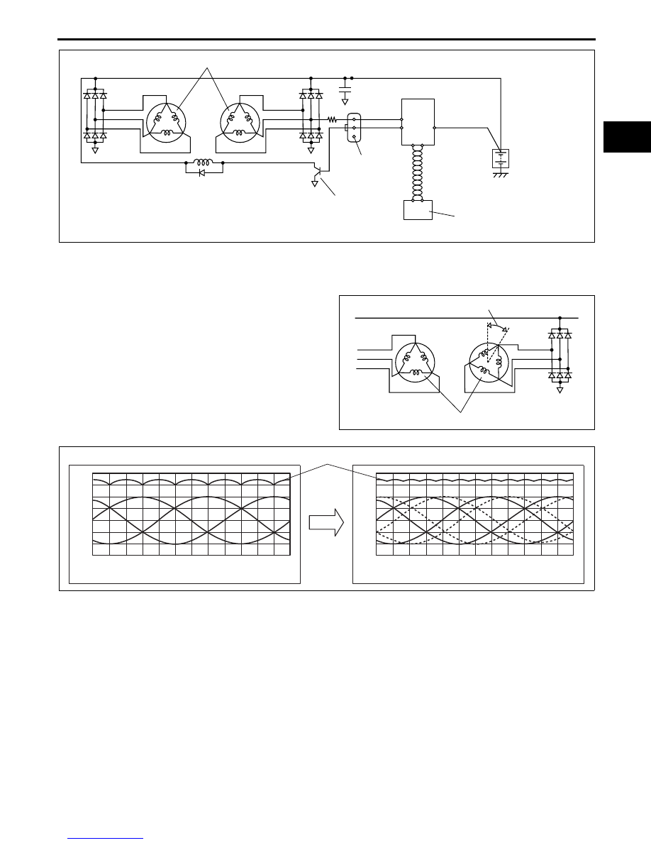
• The phase difference in the circuit of the two stator coils causes the electromagnetic pull between the rotor and 

the stator to be eliminated logically. Due to this, electromagnetic vibration and generator operation noise 
(electromagnetic noise) have been reduced.

• The pulsation occurring through voltage rectifying 

is minimized, as a result, stable voltage output is 
supplied due to the adoption of two stator coils 
with the phase difference.

• The generator warning light in the instrument cluster illuminates under the following conditions. 

— Charging system voltage problem

— Charging system voltage low

— Charging system voltage high

— IAT sensor circuit low input

— IAT sensor circuit high input

End Of Sie

B

P

D

INSTRUMENT CLUSTER
(WARNING LIGHT)

DUMMY

POWER TRANSISTOR

STATOR COIL

BATTERY

CAN

PCM

E6U117ZNB003

STATOR COIL

PHASE DIFFERENCE

E5U117ZS5004

0

0

30 60 90 120 150 180 210 240 270 300 330 360

0

30 60 90 120 150 180 210 240 270 300 330 360

0

RECTIFIED VOLTAGE

STATOR COIL (INCLUDES 1 TYPE)

STATOR COIL (INCLUDES 2 TYPE)

ANGLE (

°)

ANGLE (

°)

V

OL

T

A

GE (V)

V

OL

T

A

GE (V)

E5U117ZS5005

IGNITION SYSTEM 

01–18–1

01–18

01–18

IGNITION SYSTEM

IGNITION SYSTEM OUTLINE [LF]. . . . .  01–18–1

Features . . . . . . . . . . . . . . . . . . . . . . . .  01–18–1

IGNITION SYSTEM STRUCTURAL VIEW

[LF]  . . . . . . . . . . . . . . . . . . . . . . . . . . . .  01–18–1

IGNITION COIL

CONSTRUCTION/OPERATION
[LF]  . . . . . . . . . . . . . . . . . . . . . . . . . . . .  01–18–2

Construction  . . . . . . . . . . . . . . . . . . . . . 01–18–2
Operation  . . . . . . . . . . . . . . . . . . . . . . . 01–18–2

SPARK PLUG CONSTRUCTION 

[LF] . . . . . . . . . . . . . . . . . . . . . . . . . . . . . 01–18–3

End of Toc

IGNITION SYSTEM OUTLINE [LF]

E5U011800000N01

Features

End Of Sie

IGNITION SYSTEM STRUCTURAL VIEW [LF]

E5U011800000N02

End Of Sie

Improved reliability

• Independent ignition control system with distributorless ignition coil adopted

Improved durability

• Spark plug with an iridium alloy center electrode and platinum tip ground electrode 

adopted

IGNITION COIL

SPARK PLUG

IGNITION COIL

E5U118ZS5001

IGNITION SYSTEM 

01–18–2

IGNITION COIL CONSTRUCTION/OPERATION [LF]

E5U011818100N01

Construction

• Direct ignition coils installed directly to each spark plug have been adopted. By adopting direct ignition coils, 

high-tension leads have been eliminated in order to simplify the parts of the ignition system, preventing voltage 
reduction, and improving the firing efficiency.

• Independent firing control has been adopted to eliminate firing without spark, increasing firing energy.

• The direct ignition coil consists of an ignition coil, ignition coil connector, and boot area, which has the same 

function as the current high-tension lead.

• The igniter has been integrated into each ignition coil.

Operation

• The firing timing of the coil is controlled by the PCM for optimum ignition timing control.

Terminal layout

End Of Sie

Terminal

Signal

Three terminals

A

Ignition coil control signal

B

Ground

C

Power supply

C

B

A

NO.1

A

B

C

C

B

A

NO.2

C

B

A

NO.3

C

B

A

NO.4

PCM

IGNITION COIL

IGNITION COIL EXTERNAL VIEW

IGNITION COIL ELECTRICAL SYSTEM WIRING DIAGRAM

IGNITION COIL

IGNITION 
SWITCH

CONDENSER

CYLINDER 
NUMBER

BATTERY

BOOT

E5U118ZS5002


Content   ..  27  28  29  30   ..