Range Rover Sport. Manual - part 72


  Index      Land Rover     Range Rover Sport - service repair manual 2005-2009 year


Search            


Content   ..  70  71  72  73   ..


Range Rover Sport. Manual - part 72


Specifications 

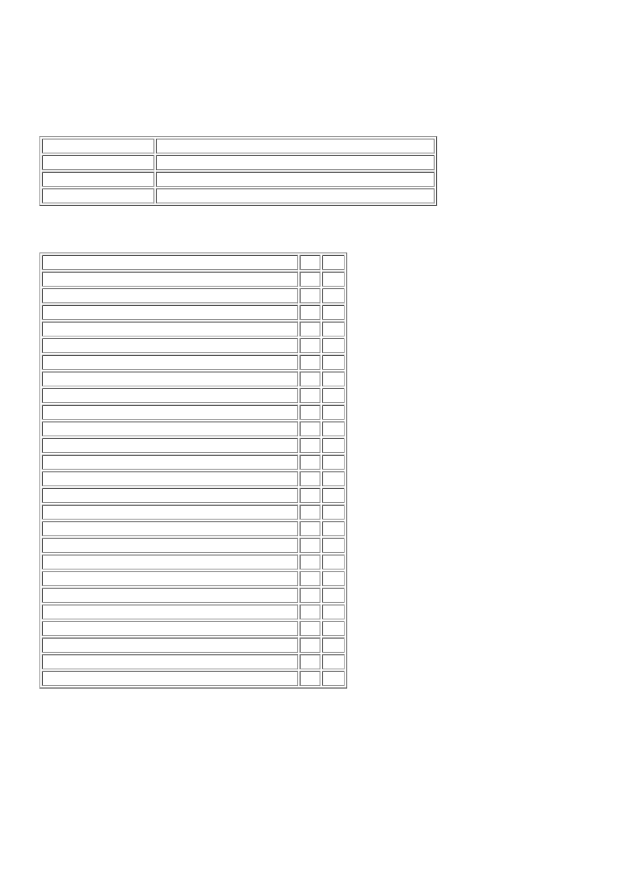
General Specifications 

Item

Specification

Dynamic Response fluid Texaco Cold Climate Fluid 14315
Capacity

2.4 Litres (4.2 pints) (2.5 US quarts)

System pressure

Variable between 3-165 bar dependant on lateral acceleration

Torque Specifications 

Description

Nm lb-ft

Dynamic Response actuator bleed screw

15

11

Dynamic Response pump bolts

22

16

Fluid pipe banjo bolt

35

26

Dynamic Response pump drive pulley bolts

22

16

Radiator access panel

10

7

Dynamic Response module

4

3

* Front actuator pipes to valve block nuts

22

16

Valve block retaining bolts

22

16

* Rear actuator pipes to valve block nuts

22

16

Dynamic Response fluid pipe securing bracket nuts/bolts 9

7

Valve block filter access plug

62

46

High pressure line intermediate union

21

15

Body mount retaining bolts

133 98

Integrated body frame bracket bolts

40

30

Integrated body frame mount nut

9

7

Upper suspension arm to wheel knuckle nut

70

52

Wheel speed sensor

9

7

Brake caliper to wheel knuckle bolt

275 203

Brake hose retaining bracket bolt

23

17

Fluid lines to actuator bolts

22

16

* Stabilizer bar link nut

175 129

Valve block transducer

25

18

Front stabilizer bar to body clamp bolts

115 85

Rear stabilizer bar to body clamp bolts

62

46

LH stabilizer bar to actuator bolts

120 89

* New nuts/bolts must be installed

Active Stabilization System Bleeding (60.60.13) 

Special Service Tools

Dynamic Response Bleed Bottle 
204-591-01 

Dynamic Response Control Box 
204-591-02 

  CAUTION: Dynamic Response system components are manufactured to very precise tolerances. It is

therefore essential that absolute cleanliness is observed when working with these components. Always install
blanking plugs to any open orifices or lines. Failure to follow this instruction may result in foreign matter ingress
to the dynamic response system.

NOTE: 


This procedure should be carried out if the following components have been removed or replaced: front or rear
stabilizer bar, front or rear valve block to actuator bar pipe assemblies, or the valve block. It is possible to bleed only
the front or rear of the system if only a stabilizer bar or pipe assembly has been removed. If the valve block has been
removed, the complete system must be bled.

1.  Check and top-up the dynamic response system fluid reservoir. 


Top-up the fluid level to the mid-way mark on the reservoir. 

2.  Install the special tool to the dynamic response reservoir. 


Completely fill the reservoir with fluid. 

Make sure the pressure regulator on the special tool is turned OFF. 


Fill the special tool bottle approximately three-quarters full with fluid. 


Connect the special tool to a suitable workshop air supply. 

3. 

  WARNING: Do not work on or under a vehicle supported only by a jack. Always support the vehicle on

safety stands.

Raise and support the vehicle. 

4.  Remove the wheels and tires. 


Remove the RH front wheel. 


Remove the rear wheels and tires. 

5. 

  CAUTION: Use a Torx socket to prevent the ball joint rotating whilst removing the nut.

  CAUTION: Note the position of the hardened steel washer. The hardened steel washer must be installed

between the stabilizer bar link and the stabilizer bar. Failure to follow this instruction may result in damage to the
vehicle.

RH front: Disconnect the stabilizer bar link. 


Remove and discard the nut. 

7.  Connect the special tool electrical connectors to the valve block. 


Connect the special tool power supply leads to the vehicle battery. 

8.  Remove the engine undershield. 

Engine Undershield (76.10.50)


9.  Connect the special tool to the front stabilizer bar bleed screws. 


Remove the bleed screw covers. 


Content   ..  70  71  72  73   ..