Frelander 2. Manual - part 350
A
-
Input shaft
C
-
Intermediate shaft 3rd - 4th
4
-
Ring gear
10
-
4th gear idler gear
12
-
3rd - 4th gear coupling sleeve
13
-
4th gear
17
-
Final drive 3rd - 4th
When 4th gear is selected, the coupling sleeve for 3rd - 4th gear is moved by a gear selector fork along the synchronizing
hub towards the 4th gear idler gear. The coupling sleeve and the synchronizing hub lock the 4th gear idler gear at the
intermediate shaft 3rd - 4th.
Engine torque is transferred to the input shaft via the clutch. The 4th gear rack on the input shaft transfers the power to
the 4th gear idler gear. From there the power is transferred to the intermediate shaft 3rd - 4th and to the final drive, which
in turn transfers power to the ring gear. The ring gear is connected to the drive shafts through the differential.
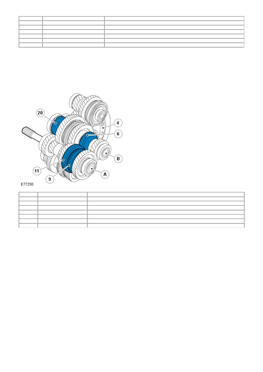
5th Gear Power Flow
Item
Part Number
Description
A
-
Input shaft
B
-
Intermediate shaft 1st - 2nd and 5th - 6th
4
-
Ring gear
6
-
5th gear
9
-
5th - 6th gear coupling sleeve
11
-
5th gear idler gear
20
-
Final drive 1st - 2nd and 5th - 6th
When 5th gear is selected, the coupling sleeve for 5th - 6th gear is moved by a gear selector fork along the synchronizing
hub towards the 5th gear idler gear. The coupling sleeve and the synchronizing hub lock the 5th gear idler gear at the
input shaft.
Engine torque is transferred to the input shaft via the clutch. The 5th - 6th coupling sleeve and 5th gear idler gear located
on the input shaft, transfer the power to the 5th gear. From there the power is transferred to the intermediate shaft 1st -
2nd and 5th - 6th and to the final drive, which in turn transfers power to the ring gear. The ring gear is connected to the
drive shafts through the differential.
6th Gear Power Flow