Frelander 2. Manual - part 194
For further details on connecting rod big-end bearing installation, refer to the relevant Service Repair Procedures (SRP).
The pistons are manufactured from aluminum alloy and are installed with 2 compression rings, and an oil control ring with
a spiral spring. A steel insert is installed in the piston upper ring groove to provide reinforcement. The piston crown is a
toroidal design that forms a pronounced bowl in the center of the piston head. Recesses are also formed in the piston
crown to provide clearance for the 4 valve heads. This design of combustion chamber promotes high levels of swirl and
turbulence required for complete combustion of the air/fuel mixture, and also improves the engine emissions.
The 3 piston rings must be installed with the ring gaps spaced at 120° (with permissible tolerance of 15° to 20°) to each
other, around the piston. The 2 upper compression rings are stamped with 'top' to aid installation. The gap of the double
beveled oil control ring must also be opposite the spiral spring joint.
The full skirt piston is coated with a graphite based substance to reduce friction with the cylinder bore. The graphite based
coating is especially important during the engine running in period and start-up. The piston also incorporates 2 oil cooling
channels that are formed on the underside of the piston head.
Two bushed holes are formed at opposite sides of the piston skirt for installation of a fully floating gudgeon pin. The
gudgeon pin passes through the piston bushed holes and connecting rod small-end, and is retained at each end with a
circlip. The piston, gudgeon pin and connecting rod small-end are supplied with oil from an oil spray jet, located below
each cylinder bore.
During installation of the pistons, the stamped direction arrow and 'DIST' on each piston crown must face toward the front
of the engine (accessory drive end).
For further details on piston and piston ring installation, refer to the relevant Service Repair Procedures (SRP) manual.
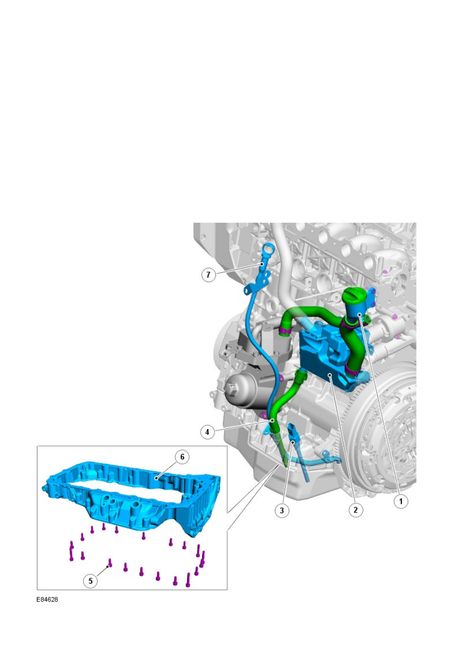
Oil Pan Housing and Oil Separator