Land Rover Discovery. Manual - part 161


  Index      Land Rover     Land Rover Discovery - service 1995-1996 year


Search            


Content   ..  159  160  161  162   ..


Land Rover Discovery. Manual - part 161


SUPPLEMENTARY RESTRAINT SYSTEM

1

FAULT DIAGNOSIS

CRASH SENSOR INSPECTION - DISTRIBUTED
SRS

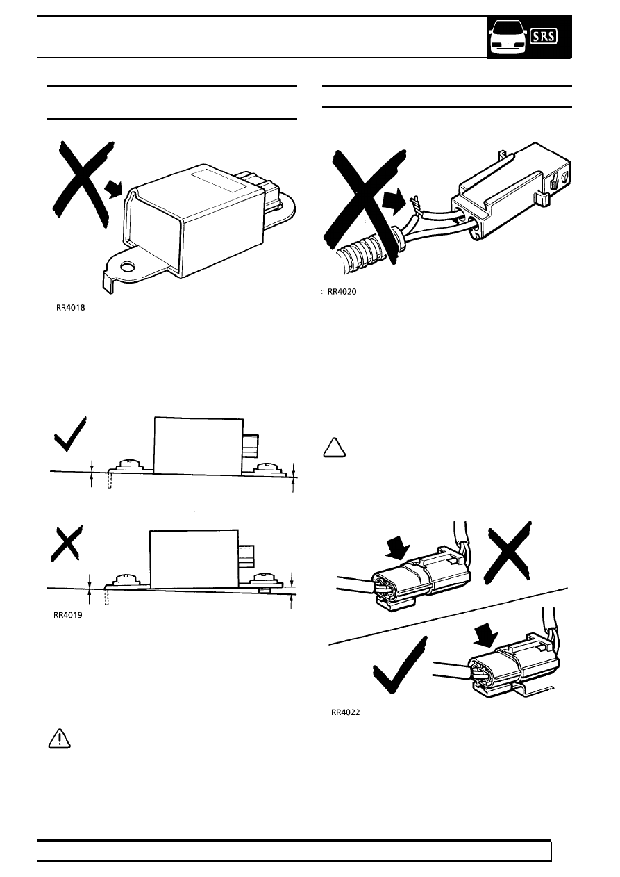
1. After any degree of front body damage, inspect

both front crash sensors. Replace a sensor if
there are any signs of dents, cracks or
deformation.

2. Ensure the sensors are installed correctly. There

must be no gap between the sensor and body of
the vehicle. Use the fixing screws supplied with
the sensor and tighten to the correct torque.
Tighten front sensor fixing before rear sensor
fixing.

CAUTION: Take extra care when painting
or doing body work in the vicinity of the
sensors. Avoid direct exposure of the

sensors or harness to heat guns, welding or
spraying equipment.

AIRBAG HARNESS

1. Never attempt to modify, splice or repair the

airbag harness. Never install electronic
equipment such as; a mobile telephone, two-way
radio or in-car entertainment system in such a
way that it interferes electrically with the airbag
harness.

NOTE: The airbag harness can be
identified by a special yellow outer
protective covering.

2. Make sure the airbag harness is installed

correctly and not pinched or trapped.

3. Ensure all airbag harness connectors are mated

correctly and securely fastened. Do not leave the
connectors hanging loose.

75

SUPPLEMENTARY RESTRAINT SYSTEM

2

FAULT DIAGNOSIS

WARNING LABELS

1. Bonnet locking platform

Refer to the Owner’s Handbook for information on the
airbag system.

2. Rotary coupler

CAUTION: Ensure wheels are straight
ahead before removal and installation.

3. Driver’s sun visor

Refer to the Owner’s Handbook for information on the
airbag system.

SUPPLEMENTARY RESTRAINT SYSTEM

3

FAULT DIAGNOSIS

4. Airbag modules

- If defective, replace and dispose of the entire unit
as directed in the instructions. Under no
circumstances should a diagnosis be performed using
electrically powered test equipment or probing
devices.

- Tampering or mishandling can result in personal
injury. For special handling instruction refer to the
Workshop manual. This airbag module cannot be
repaired. Use diagnostic instructions to determine if
the unit is defective.

- ROVER Bar code - The code number must be
recorded if the airbag module is to be replaced.

5. Steering wheel

Refer to the Owner’s Handbook for information
on the airbag system.

SUPPLEMENTARY RESTRAINT SYSTEM

1

REPAIR

SYSTEM PRECAUTIONS

CAUTION: Before and during any removal
operations within the SRS section, note
routing and position of all harnesses to aid

correct refitting and to avoid accidentally trapping
cables.

CAUTION: During refitting of any item
within the SRS section, always ensure
connectors are fully engaged and latched

before proceeding to the next stage of the
operation.

DRIVER’S AIRBAG MODULE

Service repair no - 76.74.01

WARNING: All the airbag system
components, including the wiring harness,
MUST be renewed after the airbags have

deployed.

Remove

1. Turn steering wheel 90˚ from horizontal.
2. Switch off ignition.
3. Disconnect battery negative ’-’ and then the

positive ’+’ lead.

CAUTION: Always disconnect both leads.

4. Release 2 turnbuckles and remove dash lower

panel.


Content   ..  159  160  161  162   ..