Defender 90 / 110 / 130. Manual - part 177


  Index      Land Rover     Defender 90 / 110 / 130 - service repair manual


Search            


Content   ..  175  176  177  178   ..


Defender 90 / 110 / 130. Manual - part 177


. . .  

... 

DEFENDER 

FUEL 

SYSTEM 

14.  Fit  the turbo  charger and secure with  the four 

nuts and  tighten  evenly t o  the correct torque. 

15.  connect the 

oil  feed and retum pipes t o  the 

turbo charger and tighten  the 

feed 

pipe  clamp. 

16.  Connect the boost pressure  pipe  t o  the 

piece and  secure with  the 

clip. 

17.  Connect the intercooler  h o s e  t o  t h e  turbo 

inlet. 

18.  Fit  the hose t o  air cleaner and turbo charger. 
19. 

Fit  the turbo charger elbow. 

20.  Connect the exhaust front pipe t o  t h e  elbow 

using 

t o  seal t h e  joint. 

21.  Fit  the heat  shield  and secure at t h e  

two 

fixing 

points. 

22. 

Fit  the bonnet  and  connect  the battery. 

Service Repair 

N o .  

Remove,  clean and refit. 

1 .   Remove the fan  and viscous  coupling 

assembly, 

see operation  26.25.1 

9. 

2.  Remove the fan  cowl, 

see operation  26.25.11. 

3. 

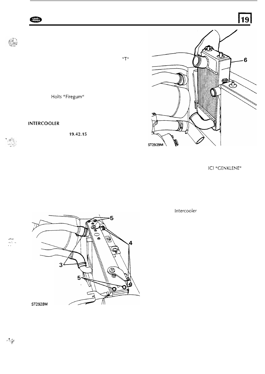
Disconnect t h e  t o p  and  bottom  hoses from 
t h e  Intercooler. 

4. 

Remove the four bolts (two each side) 
retaining  the radiator t o p  support brackets. 

5. 

Remove the four bolts 

(two each  e n d )  securing 

the radiator  surround t o p  panel,  and  remove 
t h e  panel. 

6.  Lift  out the  Intercooler. 

Cleaning. 

7. 

Flush  the intercooler  with 
propriety  cleaner,  following the manufacturers 
instructions. 

n o  

liquid  remains  in  t h e  element. 

8. 

Dry 

the Intercooler completely ensuring  that 

Refitting. 

9. 

Slide the 

into position  taking  care 

not  to damage the insulation  material  on the 
sides. 

10.  Fit  the radiator surround  t o p  panel  and  secure 

with  the four bolts. 

11. 

Fit  the 

two 

t o p  brackets  and  secure with  the 

four 

bolts. 

12.  Connect the top and  bottom hoses. 
13.  Fit  the fan  cowl. 

14. 

Fit 

the fan  and coupling assembly. 

. . 

... 

87 

COOLING 

SYSTEM 

DEFENDER 

COOLING 

SYSTEM 

Engine protection 

To prevent corrosion 

of  aluminium  engine parts  it  is 

vital  that the cooling  system 

is  filled with  a solution 

of  clean  water and  anti-freeze winter and summer. 
Never fill  o r  top-up with  water only.  always  add 
anti-freeze.  Never use salt water otherwise corrosion 

will  occur.  In  certain  territories  where the only 

available water supply may have  s o m e  salt content, 
use  only clean  rain  water o r  distilled water,  with 
anti- freeze added. 

Use  only  Universal  anti-freeze or permanent  type 

ethylene base, without methanol,  containing,  a 
suitable  inhibitor 

for aluminiium  engine parts.  Use 

o n e  part 

of anti-freeze t o  o n e  part water. 

Anti-freeze  should  be used  even  in  climates where it 
is  not necessary. 

Anti-freeze  can remain  in  t h e  cooling  system  and 
will  provide adequate protection 

for 

two 

years 

provided  that the 

specific gravity  of  the coolant 

is 

checked  before the onset 

of  the second winter and 

topped-up with  new anti- freeze as required. 

Land  Rovers leaving the factory have  the cooling 

system 

filled with  a 

50% 

anti- freeze mixture. This 

gives  protection  down t o  minus 

47 

degrees 

Centigrade  (minus 

53 

degrees Fahrenheit). 

After the second winter t h e  system  should  be 
drained  and  thoroughly  flushed.  Before  adding new 
anti-freeze  examine  all  joints and  renew defective 
hoses t o  make  sure that  t h e  system  is  leak  proof. 

See section 

09 

for 

protection  quantities. 

Service  Repair  No. 

Refilling. 

5. 

Make up a  solution 

of 

anti-freeze  and  water in 

a  separate container in  t h e  concentration 
required. 

To 

allow for topping-up, and  for 

filling the expansion tank,  prepare a quantity in 
excess 

of  the cooling system capacity. 

6 .  

Remove t h e  radiator  filler cap and  fill  t h e  
radiator until  t h e  coolant level 

is  just  below the 

filler 

neck and  refit  the cap. 

7. 

Fill 

t h e  expansion  tank to approximately half 

full  and refit  t h e  cap. 

8. 

Connect t h e  battery and run  the engine until 
normal  operating temperature 

is 

attained. 

Allow 

the engine t o  

cool completely and 

removethe radiator and  expansion tank  caps. 

If 

necessary,  top-up t h e  the radiator t o  just 
below t h e  filler neck. Top-up the expansion 

tank  t o  about half  full.  Fit  both filler  caps. 

Drain  and 

WARNING: 

D o  

not remove the radiator 

or 

expansion tank  filler cap when the engine 

is 

hot because the cooling system 

is 

pressurized and personal  scalding  could 
result. 

1. 

Disconnect the battery. 

2. 

Disconnect the bottom  coolant  hose from  the 
radiator.  Allow  t o  drain  and  reconnect the 
hose. 

3. 

To 

drain  the cylinder block,  remove the drain 

plug which  is  situated o n  t h e  left  hand 

side of 

the engine immediately below front 

core plug. 

Refit  t h e  plug,  with  a  new washer, when t h e  

draining  is  completed. 

4. 

To  drain  the expansion  tank,  remove the cap 
and disconnect the expansion  hose from  the 
radiator  and  allow  it  t o  drain  into a suitable 
container.  Flush  the tank with  clean water  and 
reconnect the hose. 

_,’ 

88 

DEFENDER 

SYST

E

FAN COWL 

26 

Service  Repair 

No.  26.25.11 

Remove  and refit. 

1 .   Follow instructions 

t o  7 operation  26.25.19. 

Remove t h e  cowl  from  t h e  engine 

compartment. 

Refitting. 

3. 

Reverse instructions 

and  2. 

FAN 

AND  COUPLING ASSEMBLY 

Service  Repair 

N o .  26.25.19 

Remove  and  refit. 

1. 

Disconnect  t h e  battery for safety reasons. 

2.  Drain  the coolant by  disconnecting the radiator 

bottom  h o s e  and  reconnect when  coolant has 
drained. 
Remove  the t o p  hose. 
Using  a cranked  o p e n  e n d e d  spanner and  a 
restraining  bar  in  the hole  in  the pulley  hub, 
release  anti-clockwise,  the viscous  coupling 

from the water pump  spindle.  Lower the fan 
and  coupling assembly into the base 

of the 

cowl. 

5. 

Remove t h e  two nuts securing  the cowl  t o  the 
radiator. 

Refitting 

8. 

9. 

10. 

Insert  the fan  and coupling into the base 

of 

the cowl  reversing t h e  removal  procedure. 

Fit  the coupling  t o  t h e  water pump spindle 
noting  that it  has a left  hand  thread.  Tighten 

the coupling  using  t h e  restraining  bar  and 
cranked  spanner. 

Fit  the cowl and  secure with  the two  nuts. 
Ensure  that the cowl fits properly  in  its  lower 

location. 
Fit  the t o p  hose and refill  the cooling  system 

with  the correct concentration 

of  anti-freeze 

and water. 
Connect the battery,  run  the engine and check 
for 

coolant leaks. 

6 .  

Lift 

the cowl t o  release 

it 

from  its  lower 

location. 

7. 

Move the cowl  forward,  towards the engine 

from the gap created  between the 

cowl 

and 

radiator. 

89 

RADIATOR 

Service  Repair 

No. 

26.40.01 

Remove 

and  refit 

Remove the fan  and viscous  coupling 

assembly, 

see 

operation 26.25.19. 

2.  Remove the fan 

cowl, 

see operation 

3. 

Disconnect  the h o s e s  from  the intercooler. 

4. 

Disconnect  the expansion  tank  hose from the 
radiator. 

5.  Disconnect  the 

oil 

cooler pipes  from  the 

radiator and  cover t h e  ends 

to prevent  entry 

of 

dirt. 

6 .  

Disconnect  the b o t t o m  hose from  the radiator. 

Remove the four bolts,  two each side, 
retaining t h e  radiator  t o p  securing  brackets, 
and  remove the  brackets. 

intercooler. 

8. 

Lift  o u t  the radiator complete with  the 


Content   ..  175  176  177  178   ..