Defender 90 / 110 / 130. Manual - part 178


  Index      Land Rover     Defender 90 / 110 / 130 - service repair manual


Search            


Content   ..  176  177  178  179   ..


Defender 90 / 110 / 130. Manual - part 178


9. 

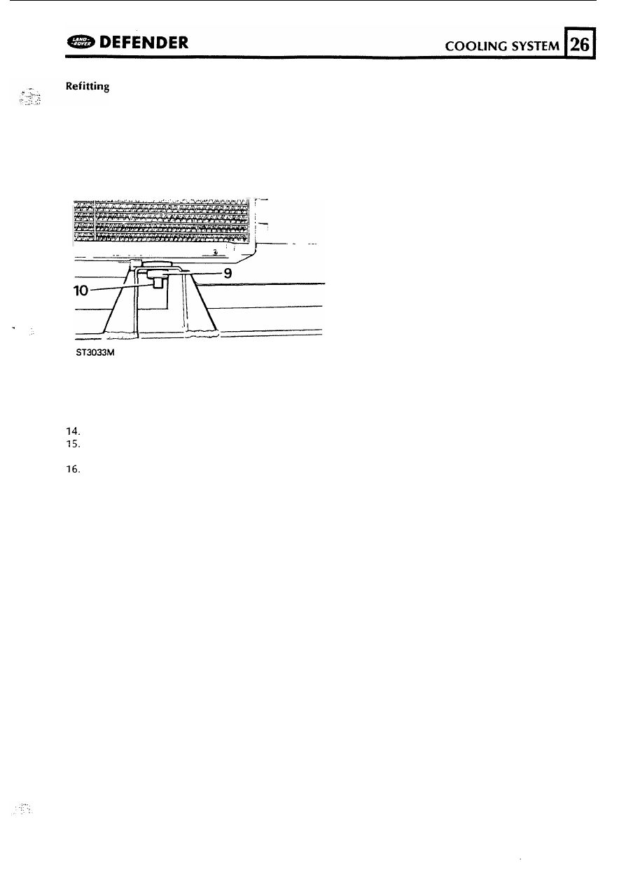
Check that the rubber grommets on the 

radiator locating pegs and beneath the radiator 

mounting brackets on the chassis cross 

member are 

in position. 

10.  Lower the radiator into position ensuring that 

the pegs locate in the mounting brackets. 

11. 

Fit the radiator top mounting brackets and 

secure with the four bolts. 

12.  Connect 

the 

radiator bottom hose. 

13.  Fit the oil cooler pipes to the radiator. 

Connect the expansion tank  hose. 

Connect the top and bottom hoses to the 

intercooler. 

Place the fan  cowl in position but do not 

secure at  this stage. 

17.  Fit the fan and viscous coupling and secure 

the 

cowl with the two nuts. 

18.  Check that all the coolant hose 

clips 

are tight 

and refill the cooling system with the correct 

concentration 

of 

water and anti-freeze, 

see 

operation 26.10.01. 

91 

26 

WATER 

PUMP 

Service  Repair 

No. 

26.50.01 

Remove a n d  refit 

DEFENDER 

CO

OLING 

SYSTEM 

1. 

2. 
3. 

4. 

Remove  the fan  and coupling  assembly 

operation  2.  25.19. 
Remove  the fan 

cowl  operation 26.25.11. 

Slacken  the fan  belt tension and  remove it 
from t h e  pulley. 

Remove  the four bolts securing pulley t o  hub. 

5. 

6 .  

7. 

8. 

Remove the thermostat  housing  t o  water 
pump hose. 
Disconnect the bottom  hose from  the water 

Remove the 

six 

bolts and o n e  nut  securing the 

water  p u m p  t o  t h e  front cover plate. 

Remove the water  p u m p  and gasket. 

Refitting 

9. 

11. 

12. 

13. 

15. 
16. 
17. 
18. 

19. 

Clean the water pump and  front  cover plate 

mating  faces. 
Lightly grease a  new gasket and  place  in 
position  on the 

cover plate. 

Clean t h e  threads 

of 

the water pump retaining 

bolts and  apply  Loctite  572 thread  lubricant 

sealant  t o  the threads 

of 

all  the bolts. 

Fit  the pump 

to 

the engine and  secure with 

t h e  six  bolts  and o n e  nut in  accordance with 
t h e  chart  below.  Tighten t h e  fixings evenly and 
t o  the correct torque. 
Connect the bottom hose t o  the water pump. 
Fit  the pulley t o  the water pump hub and 
secure with  the four bolts. 
Fit  and tension  the water 

belt. 

Fit  the fan  cowl. 
Fit  the fan  and  coupling  assembly. 

Check that all  t h e  coolant hose clips are tight 
and 

refill  the cooling  system  with  the correct 

concentration 

of  water and  anti-freeze,  s e e  

operation 
Connect the battery,  run  t h e  engine and check 
for coolant  leaks. 

92 

DEFENDER 

M

A

NI

FOL

D

AND 

EXHA

U

ST 

EXHAUST 

AND 

INLET 

MANIFOLDS 

Service Repair 

No. 30.15.01 

Remove  and  refit 

Note: 

to 

remove the inlet manifold, the exhaust 

mainifold must 

b e  

removed first. 

1. 

Disconnect  the battery. 

2. 

Remove t h e  air cleaner 

to turbo charger inlet 

hose from the turbo charger. 

3. 

Disconnect  hose from  turbo charger t o  
intercooler. 

4. 

Remove t h e  turbo  charger heat shield. 
Disconnect  from  the turbo charger, the oil 

feed pipe. 

6. 

Disconnect  t h e  front  exhaust  pipe  from  the 

turbo  charger elbow. 

7. 

Release  the front  exhaust pipe  bracket  from 

the cylinder  block. 

8. 

Disconnect  the front  exhaust 

pipe  from the 

forward  silencer pipe. 
Release  the heater rail  from t h e  exhaust 
manifold  studs. 

10.  Disconnect  the boost  pressure 

pipe 

from  the 

turbo  charger. 

11.  Disconnect the turbo  charger 

oil  drain  pipe 

from  the cylinder block. 

12.  Remove  the exhaust 

nuts and 

withdraw the manifold  complete with  t h e  
turbo charger. 

Inlet  manifold 

13.  Disconnect hose from  inlet  manifold 
14.  Remove the 

two 

bolts and  two  nuts and 

withdraw the inlet  manifold. 

15.  Remove the common gasket. 

Continued 

93 

MANIFOLDS AND  EXHAUST 

DEFENDER 

Ref 

16. 

17. 

18. 

19. 

20. 

21. 
22. 

24. 

25. 

26. 

27. 

Place  a  new gasket in  position  and  fit  the inlet 

manifold  and secure with  the two bolts  and 
two 

nuts and tighten  t o  the correct torque. 

Fit  t h e  exhaust manifold  complete with  turbo 

charger and secure with  the nuts. 
Fit  t h e  heater rail  t o  t h e  manifold  studs. 
Connect t h e  turbo charger 

oil 

drain  pipe  t o  

the cylinder block. 
Connect t h e  boost pressure  pipe t o  the turbo 
charger. 
Using 

GUM" 

fit  the front 

exhaust  pipe t o  t h e  turbo charger elbow and 
secure with  the clamp.  Note,  before fitting the 
pipe t o  t h e  elbow make sure that the securing 
clamp 

is 

above t h e  inlet  manifold  since the clip 

will  not 

pass  between  the front  pipe and 

manifold. 
Connect t h e  front pipe t o  the forward  silencer. 
Fit-the front pipe support bracket  t o  the 
cylinder block with  t h e  single bolt. 
Connect t h e  turbo charger oil  feed pipe. 
Fit  t h e  intercooler t o  turbo charger hose. 
Fit  t h e  air  cleaner t o  turbo  charger hose. 
Fit  t h e  turbo charge heat  shield. 
Connect t h e  battery,  run  the engine and  check 
for 

exhaust 

gas  leaks. 

94 


Content   ..  176  177  178  179   ..