Defender 90 / 110 / 130. Manual - part 113


  Index      Land Rover     Defender 90 / 110 / 130 - service repair manual


Search            


Content   ..  111  112  113  114   ..


Defender 90 / 110 / 130. Manual - part 113


STEERING 

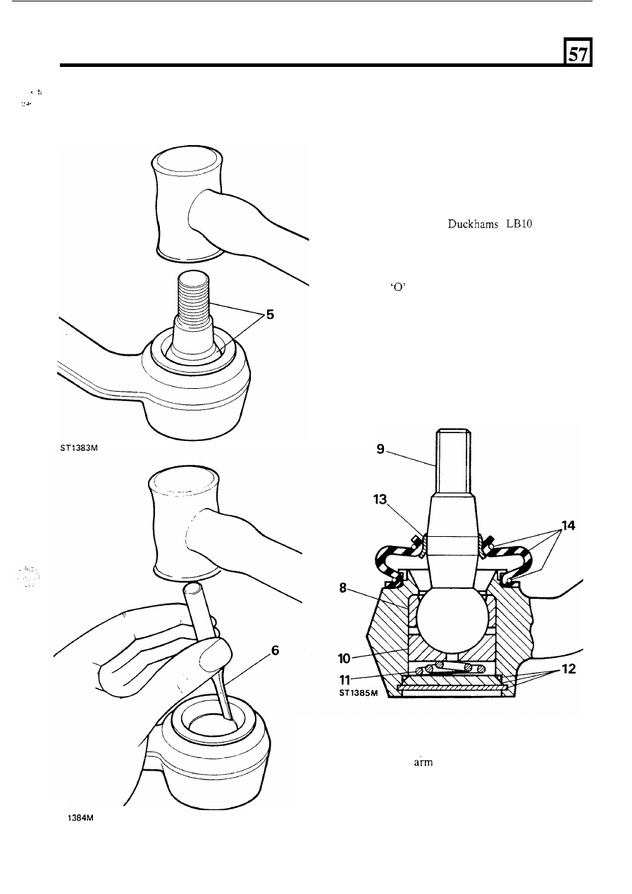
5 .   Since  the  ball  pin  cannot  be  removed  with  the 

ball  pin  to release  the  retainer  and  to remove  the 
pin from the housing. 

6. 

Using  a  sharp-edged  punch  or chisel,  drive  the 

retainer  in  position,  tap  the  threaded  end  of  the 

ball  lower  socket  from  the  housing.  Should 

difficulty be experienced, apply gentle heat to the 
housing  and  then  continue  to  drive  the  socket 
from the housing. 

7. 

Clean the housing and remove any burrs. 

Assemble 

8. 

Press-in  the  lower  socket  squarely  up  to  the 

shoulder. 

9. 

Dip  the  ball  in 

grease,  or 

equivalent  and  fit  to  the  housing  and  pack  with 
grease. 

10. 

Fit the top socket. 

11.  Fit the spring, small diameter towards the ball. 
12.  Fit the 

ring  and  using  the same method  as 

for 

removing  the circlip and  compress  the cover plate 
and  secure with  the circlip.  Ensure that  the circlip 

is fully seated in the machined groove. 

13.  Press the retainer on to the ball pin 

so that the top 

edge is level with the edge 

of  the taper. 

14. 

Fit  the  dust  cover  and  retain  with  the  two  spring 
rings. 

ST 

15.  Fit  the  drop 

to  the  steering  box  using  a  new 

lock  washer.  Tighten  the  retaining  nut  to  the 

correct torque and bend over the lock washer. 

16.  Assemble  the  ball  pin  to  the  drag  link,  see 

instructions for fitting  drag link and track  rod, and 
tighten  the  castle  nut 

to 

the  correct  torque  and 

secure with a new split pin. 

45 

STEERING 

TRACK 

ROD 

AND 

Models 

When adjusting or renewing a track rod or draglink it 

is 

important to ensure that t h e  ball joints are assembled 

in 

the  same angular plane and  that  the  ball  joint pins  are 
central 

in  their  respective  housings,  as  example  ‘A’ 

illustrated  below.  Premature  wear  could  result  if  the 
pins are inclined to one-side as illustration 

CAUTION: A  track rod or draglink that is damaged or 
bent  must  be  renewed.  No  attempt should 

be  made  to 

repair 

or straighten it. 

46 

SUSPENSION 

OVERHAUL FRONT HUB ASSEMBLY 

Service tools: 
Drift 

134 

Hub oil seal replacer 

1349 

Dial gauge bracket 

RO 

530106 

DISMANTLE 

13. 

Remove the key washer. 

14.  Withdraw  the  hub  and  brake  disc  assembly 

complete with bearings. 

15.  Remove the outer bearing. 

16. 

Mark, for reassembly, the relationship between the 

17. 

Remove  the  five bolts  and  separate the hub  from 

hub and brake disc, 

if 

original hub is to be refitted. 

the brake disc. 

Slacken road wheel nuts. 

2.  Jack up the vehicle and lower onto axle stand. 
3.  Remove the road wheel. 
4.  Slacken the lock nuts securing the jump hose to the 

retaining bracket. 

continued 

5 .  

Remove  the  two  bolts  securing  the  brake  caliper 

and whilst  withdrawing the caliper from  the brake 
disc  release  the  jump  hose  from  the  bracket. 

Tie 

the caliper securely to one side. 

NOTE: The road wheel retaining studs must not be 
renewed.  Should  any  studs  be  unservicable  a  new 
hub complete with studs must be obtained. 

KEY TO HUB ASSEMBLY 

NOTE:  Since  the  bracket 

on 

later  vehicles  is  not 

completely. 

open-ended, 

the 

caliper  must 

be 

removed 

6.  Lever-off the dust cap. 

7. 

Remove the circlip from the drive shaft. 

8.  Remove the drive shaft shim. 

9. 

Remove  the 

five  bolts  and  withdraw  the  driving 

member and joint washer. 

10.  Bend back the lock washer tab. 
11.  Remove the locknut and tab washer. 
12.  Remove the hub adjusting nut. 

1.  Dust cap. 

2.  Drive shaft circlip. 
3.  Drive shaft shim 
4.  Drive member. 

5. 

Drive member joint washer. 

6. 

Drive member retaining bolt (five off). 

7.  Locknut. 

Lock washer. 

9.  H u b  adjusting nut. 

10.  Keyed washer. 

11.  Outer 
12.  Hub. 
13.  Inner bearing. 
14.  Grease seal. 

15.  Brake disc. 

SUSPENSION 

18.  Drift-out  the  grease  seal  and  inner  bearing  from 

19.  Drift-out the inner and outer bearing tracks. 

22.  With  the lip side leading  fit  a  new  seal  to the hub 

using  special  tool 

18G 1349  grease  seal  replacer 

and  drift  18G 134. 

the  seal 

so 

that 

it 

is 

recessed 

to 

(0.190 

to 

0.210 in) below 

the  rear  face  of  the  hub.  Apply  grease  liberally 
between the seal lips and springs. 

the hub and discard the seal. 

23.  Assemble  the  brake  disc  to the  hub  lining  up  the 

marks made during dismantling. Fit and tighten the 
five retaining bolts to 65 to 

(48 to 59 Ibf  ft). 

24.  Grease as in instruction 21 and fit the outer bearing 

to the hub. 

25.  Clean  the stub axle and  drive shaft and fit  the hub 

assembly to the axle. 

26.  Fit the key washer. 
27. 

Fit the hub adjusting nut and tighten by hand whilst 
rotating the hub until  all end-play 

is taken up. 

28.  Mount  a  dial  gauge 

using  bracket 

R O  

530106 and 

rest  the  stylus  in  a  loaded  condition 

on 

the 

adjusting nut. 

ASSEMBLE 

20. 

Clean  and  degrease the  hub  and 

the  inner 

and outer bearing tracks. 

continued 

ST6 

21.  Pack  the  hub  inner  bearing  with  a  grease 

recommended 

the lubrication  chart and fit to the 

hub.  Use a minimum 

of 

grams 

of  grease. 


Content   ..  111  112  113  114   ..