Defender (1999-2002). Manual - part 12
MAINTENANCE
3
MAINTENANCE
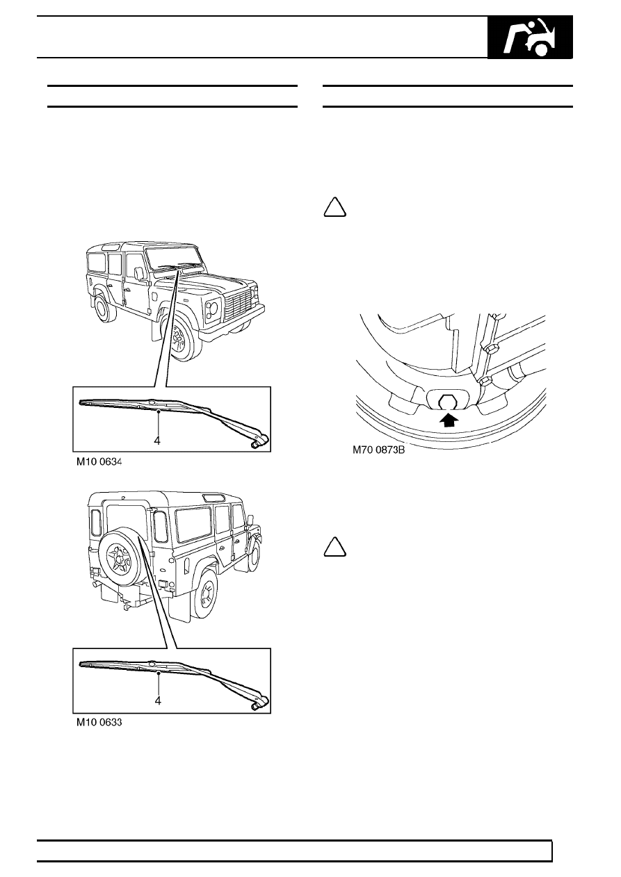
WIPERS AND WASHERS
1. Operate screen washer and switch on wipers.
Check washer jets are correctly aimed and
check for smooth smearless operation across
screen of wiper blades at all speeds, including
intermittent.
2. Repeat operation for rear screen
wipers/washers.
3. Check all wiper blades for condition and signs of
splits or damage.
4. Check security of wiper arms.
HANDBRAKE
1. With the vehicle stationary, apply handbrake and
check for correct operation. See BRAKES,
Adjustment.
2. Release handbrake and check for correct
operation.
NOTE: Any adjustment required as a result
of the checking process will be subject to
additional labour and/or material cost and
should not be carried out without the
authorisation of the customer.
Adjust handbrake (First 12,000 miles/12 months
only
1. Adjust handbrake cable. See BRAKES,
Adjustment.
NOTE: Additional time is built into the first
12,000/12 months service time to allow for
handbrake cable adjustment.