Jeep XJ. Manual - part 415


  Index      Jeep     Jeep XJ - service repair manual 2001 year


Search            


Content   ..  413  414  415  416   ..


Jeep XJ. Manual - part 415


(4) Inspect the pump bushing. Then check the

reaction shaft support bushing. Replace either bush-
ing only if heavily worn, scored or damaged. It is not
necessary to replace the bushings unless they are
actually damaged.

(5) Install the gears in the pump body and mea-

sure pump component clearances as follows:

(a) Clearance between outer gear and reaction

shaft housing should be 0.010 to 0.063 mm (0.0004
to 0.0025 in.). Clearance between inner gear and
reaction shaft housing should be 0.010 to 0.063
mm (0.0004 to 0.0025 in.). Both clearances can be
measured at the same time by:

(I) Installing the pump gears in the pump

housing.

(II) Position an appropriate piece of Plasti-

gage

y across both gears.

(III) Align the plastigage to a flat area on the

reaction shaft housing.

(IV) Install the reaction shaft to the pump

housing.

(V) Separate the reaction shaft housing from

the pump housing and measure the Plastigage

y

following the instructions supplied with it.
(b) Clearance between inner gear tooth and

outer gear should be 0.08 to 0.19 mm (0.0035 to
0.0075 in.). Measure clearance with an appropriate
feeler gauge.

(c) Clearance between outer gear and pump

housing should also be 0.010 to 0.19 mm (0.0035 to
0.0075 in.). Measure clearance with an appropriate
feeler gauge.

FRONT CLUTCH

Clean and inspect the front clutch components.

Replace the clutch discs if warped, worn, scored,

burned or charred, or if the facing is flaking off.
Replace the steel plates if heavily scored, warped, or
broken. Be sure the driving lugs on the plates are in
good condition. The lugs must not be bent, cracked or
damaged in any way.

Replace the clutch spring and spring retainer if

either is distorted, warped or broken.

Check the lug grooves in the clutch retainer. The

steel plates should slide freely in the slots. Replace
the retainer if the grooves are worn or damaged.

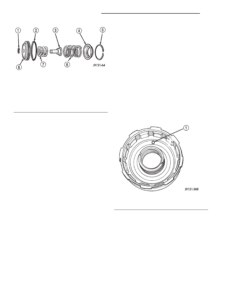
Check action of the check ball in the retainer (Fig.

226). The ball must move freely and not stick.

NOTE: Inspect the clutch retainer bushings care-
fully (Fig. 227). The retainer bushings are NOT ser-
viceable. It will be necessary to replace the retainer
if either bushing is scored, or worn.

Inspect the piston and retainer seal surfaces for

nicks or scratches. Minor scratches can be removed
with crocus cloth. However, replace the piston and/or
retainer if the seal surfaces are seriously scored.

REAR CLUTCH

Clean the clutch components with solvent and dry

them with compressed air.

Check condition of the input shaft seal rings. It is

not necessary to remove or replace rings unless they
are broken, cracked, or no longer securely hooked
together.

Inspect the input shaft splines and machined sur-

faces. Very minor nicks or scratches can be smoothed
off with crocus cloth. replace the shaft if the splines
are damaged, or any of the machined surfaces are
severely scored.

Fig. 225 Rear Servo Components

1 – SNAP RING
2 – PISTON SEAL
3 – PISTON PLUG
4 – SPRING RETAINER
5 – SNAP RING
6 – PISTON SPRING
7 – CUSHION SPRING
8 – PISTON

Fig. 226 Front Clutch Piston Retainer Check Ball

Location

1 – RETAINER CHECK BALL

21 - 196

AUTOMATIC TRANSMISSION—30RH

XJ

CLEANING AND INSPECTION (Continued)

Replace the clutch discs if warped, worn, scored,

burned/charred, the lugs are damaged, or if the fac-
ing is flaking off.

Replace the steel plates and the pressure plate if

heavily scored, warped, or broken. Be sure the driv-
ing lugs on the discs and plates are also in good con-
dition. The lugs must not be bent, cracked or
damaged in any way.

Replace the piston spring and wave spring if either

part is distorted, warped or broken.

Check the lug grooves in the clutch retainer. The

steel plates should slide freely in the slots. Replace
the retainer if the grooves are worn or damaged. Also
check action of the retainer check ball. The ball must
move freely and not stick.

Inspect the piston and retainer seal surfaces for

nicks or scratches. Minor scratches can be removed
with crocus cloth. However, replace the piston and/or
retainer if the seal surfaces are seriously damaged.

Check thrust washer condition. Washer thickness

should be 1.55 to 1.60 mm (0.061 to 0.063 in.).
Replace the washer if worn or damaged.

Check condition of the two seal rings on the input

shaft and the single seal ring on the piston retainer
hub. Replace the seal rings only if severely worn,
cracked, or cannot be hooked together.

PLANETARY GEARTRAIN/OUTPUT SHAFT

Clean the intermediate shaft and planetary compo-

nents in solvent and dry them with compressed air.
Do not spin the planetary pinion gears with com-
pressed air.

Inspect the planetary gear sets and annulus gears.

The planetary pinions, shafts, washers, and retaining
pins are serviceable. However, if a pinion carrier is
damaged, the entire planetary gear set must be
replaced as an assembly.

Replace the annulus gears if the teeth are chipped,

broken, or worn, or the gear is cracked. Replace the
planetary thrust plates and the tabbed thrust wash-
ers if cracked, scored or worn.

Inspect the machined surfaces of the output shaft.

Be sure the oil passages are open and clear. Replace
the shaft if scored, pitted, or damaged.

Inspect the sun gear and driving shell. If either

component is worn or damaged, remove the sun gear
rear retaining ring and separate the sun gear and
thrust plate from the driving shell. Then replace the
necessary component.

Replace the sun gear as an assembly if the gear

teeth are chipped or worn. Also replace the gear as
an assembly if the bushings are scored or worn. The
sun gear bushings are not serviceable. Replace the
thrust plate if worn, or severely scored. Replace the
driving shell if distorted, cracked, or damaged in any
way.

Replace all snap rings during geartrain assembly.

Reusing snap rings is not recommended.

ADJUSTMENTS

GEARSHIFT CABLE

Check adjustment by starting the engine in Park

and Neutral. Adjustment is OK if the engine starts
only in these positions. Adjustment is incorrect if the
engine starts in one but not both positions. If the
engine starts in any position other than Park or Neu-
tral, or if the engine will not start at all, the park/
neutral position switch may be faulty.

Gearshift Adjustment Procedure

(1) Shift transmission into Park.
(2) Raise vehicle.
(3) Release cable adjuster clamp (at transmission

end of cable) to unlock cable.

(4) Unsnap cable from cable mounting bracket on

transmission (Fig. 228).

(5) Slide cable eyelet off transmission shift lever.
(6) Verify transmission shift lever is in Park

detent by moving lever fully rearward. Last rearward
detent is Park position.

(7) Verify positive engagement of transmission

park lock by attempting to rotate propeller shaft.
Shaft will not rotate when park lock is engaged.

(8) Slide cable eyelt onto transmission shift lever.
(9) Snap

shift

cable

adjuster

into

mounting

bracket on transmission.

(10) Lock shift cable by pressing cable adjuster

clamp down until it snaps into place.

(11) Lower vehicle and check engine starting.

Engine should start only in Park and Neutral.

Fig. 227 Retainer Bushing Location/Inspection

1 – FRONT CLUTCH RETAINER BUSHINGS (NON-

SERVICEABLE)

XJ

AUTOMATIC TRANSMISSION—30RH

21 - 197

CLEANING AND INSPECTION (Continued)

BRAKE TRANSMISSION SHIFT INTERLOCK
CABLE ADJUSTMENT

(1) Shift transmission into PARK.
(2) Remove shift lever bezel and console screws.

Raise bezel and console for access to cable.

(3) Pull cable lock button up to release cable (Fig.

229).

(4) Turn ignition switch to LOCK position.
(5) Use a spacer to create a one millimeter gap

between the shifter pawl and top of the shift gate.

(6) Pull cable forward. Then release cable and

press cable lock button down until it snaps in place.

(7) Check adjustment as follows:

(a) Check movement of release shift handle but-

ton (floor shift) or release lever (column shift). You
should not be able to press button inward or move
column lever.

(b) Turn ignition switch to RUN position.
(c) Shifting out of park should not be possible.
(d) Apply the brake and attempt to shift out of

PARK. Shifting should be possible.

(e) While the transmission is shifted out of

PARK, release the brake and attempt to shift
through all gears. Release the shift button at least
once during this procedure. The ignition key should
not go to the LOCK position.

(f) Return transmission to the PARK position

without applying the brake.
(8) Move shift lever back to PARK and check igni-

tion switch operation. You should be able to turn
switch to LOCK position and shift lever release but-
ton/lever should not move.

TRANSMISSION THROTTLE VALVE CABLE
ADJUSTMENT

The transmission throttle valve is operated by a

cam on the throttle lever. The throttle lever is oper-
ated by an adjustable cable (Fig. 230). The cable is
attached to an arm mounted on the throttle lever
shaft. A retaining clip at the engine-end of the cable
is removed to provide for cable adjustment. The
retaining clip is then installed back onto the throttle
valve cable to lock in the adjustment.

A correctly adjusted throttle valve cable will cause

the throttle lever on the transmission to move simul-
taneously with the throttle body lever from the idle
position. Proper adjustment will allow simultaneous
movement without causing the transmission throttle
lever to either move ahead of, or lag behind the lever
on the throttle body.

Checking Throttle Valve Cable Adjustment

(1) Turn ignition key to OFF position.
(2) Remove air cleaner.
(3) Verify that lever on throttle body is at curb idle

position. Then verify that transmission throttle lever
(Fig. 231) is also at idle (fully forward) position.

(4) Slide cable off attachment stud on throttle body

lever.

(5) Compare position of cable end to attachment

stud on throttle body lever:

Fig. 228 Shift Cable Attachment At

Transmission–Typical

1 – THROTTLE VALVE CABLE
2 – TRANSMISSION SHIFT LEVER
3 – SHIFT CABLE
4 – SHIFT CABLE BRACKET

Fig. 229 Park Lock Cable Attachment

1 – PARK LOCK CABLE
2 – CABLE LOCK BUTTON
3 – SHIFT LEVER ASSEMBLY
4 – SHIFT CABLE

21 - 198

AUTOMATIC TRANSMISSION—30RH

XJ

ADJUSTMENTS (Continued)

• Cable end and attachment stud should be

aligned (or centered on one another) to within 1 mm
(0.039 in.) in either direction.

• If cable end and attachment stud are misaligned

(off center), cable will have to be adjusted as
described in Throttle Valve Cable Adjustment proce-
dure.

(6) Reconnect cable end to attachment stud. Then

with aid of a helper, observe movement of transmis-
sion throttle lever and lever on throttle body.

• If both levers move simultaneously from idle to

half-throttle and back to idle position, adjustment is
correct.

• If transmission throttle lever moves ahead of, or

lags behind throttle body lever, cable adjustment will
be necessary. Or, if throttle body lever prevents
transmission lever from returning to closed position,
cable adjustment will be necessary.

Throttle Valve Cable Adjustment Procedure

(1) Turn ignition switch to OFF position.
(2) Remove air cleaner if necessary.
(3) Disconnect cable end from attachment stud.

Carefully slide cable off stud. Do not pry or pull
cable off.

(4) Verify that transmission throttle lever is in

fully closed position. Then be sure lever on throttle
body is at curb idle position.

(5) Insert a small screwdriver under edge of

retaining clip and remove retaining clip.

(6) Center cable end on attachment stud to within

1 mm (0.039 in.).

NOTE: Be sure that as the cable is pulled forward
and centered on the throttle lever stud, the cable
housing moves smoothly with the cable. Due to the
angle at which the cable housing enters the spring
housing, the cable housing may bind slightly and
create an incorrect adjustment.

(7) Install retaining clip onto cable housing.
(8) Check cable adjustment. Verify transmission

throttle lever and lever on throttle body move simul-
taneously.

FRONT BAND ADJUSTMENT

The front (kickdown) band adjusting screw is

located on the left side of the transmission case
above the manual valve and throttle valve levers.

(1) Raise vehicle.
(2) Loosen band adjusting screw locknut (Fig. 232).

Then back locknut off 3-5 turns. Be sure adjusting
screw turns freely in case. Apply lubricant to screw
threads if necessary.

(3) Tighten band adjusting screw to 8 N·m (72 in.

lbs.) torque with Inch Pound Torque Wrench C-3380-A,
a 3-in. extension and appropriate Torx socket.

CAUTION: If Adapter C-3705 is needed to reach the
adjusting screw, tighten the screw to only 5 N·m
(47-50 in. lbs.) torque.

(4) Back off front band adjusting screw 2-1/2

turns.

(5) Hold adjuster screw in position and tighten

locknut to 41 N·m (30 ft. lbs.) torque.

(6) Lower vehicle.

Fig. 230 Throttle Cable Attachment At Engine

1 – TRANSMISSION THROTTLE VALVE CABLE
2 – ACCELERATOR CABLE
3 – CABLE ENGINE BRACKET
4 – THROTTLE BODY
5 – CABLE GUIDE

Fig. 231 Throttle Cable Attachment At Transmission

1 – RETURN SPRING
2 – THROTTLE VALVE CABLE
3 – THROTTLE VALVE CABLE BRACKET
4 – THROTTLE VALVE LEVER
5 – GEAR SELECTOR LEVER
6 – SHIFT CABLE BRACKET

XJ

AUTOMATIC TRANSMISSION—30RH

21 - 199

ADJUSTMENTS (Continued)


Content   ..  413  414  415  416   ..