Jeep XJ. Manual - part 414


  Index      Jeep     Jeep XJ - service repair manual 2001 year


Search            


Content   ..  412  413  414  415   ..


Jeep XJ. Manual - part 414


Clean the valve body components in a parts clean-

ing solution only. Do not use gasoline, kerosene, or
any type of caustic solution. Dry the parts with com-
pressed air. Make sure all passages are clean and
free from obstructions.

NOTE: Do not use rags or shop towels to wipe off
valve body components. Lint from these materials
will adhere to the valve body components. Lint will
interfere with valve operation and may clog filters
and fluid passages.

Inspect the throttle and manual valve levers and

shafts. Do not attempt to straighten a bent shaft or
correct a loose lever. Replace these components if
worn, bent, loose or damaged in any way.

Inspect all of the valve body mating surfaces for

scratches, nicks, burrs, or distortion. Use a straight-
edge to check surface flatness. Minor scratches may

be removed with crocus cloth using only very light
pressure.

Minor distortion of a valve body mating surface

may be corrected by smoothing the surface with cro-
cus cloth. The cloth should be in sheet form and be
positioned on a surface plate, sheet of plate glass, or
equally flat surface. However, if distortion is severe
or any surfaces are heavily scored, the valve body
will have to be replaced.

CAUTION: Many of the valve body valves and plugs
are made of coated aluminum. Aluminum compo-
nents can be identified by the dark color of the spe-
cial coating applied to the surface (or by testing
with a magnet). DO NOT polish or sand aluminum
valves or plugs with any type of material, or under
any circumstances. This practice might damage the
special coating and cause the valves and plugs to
stick and bind.

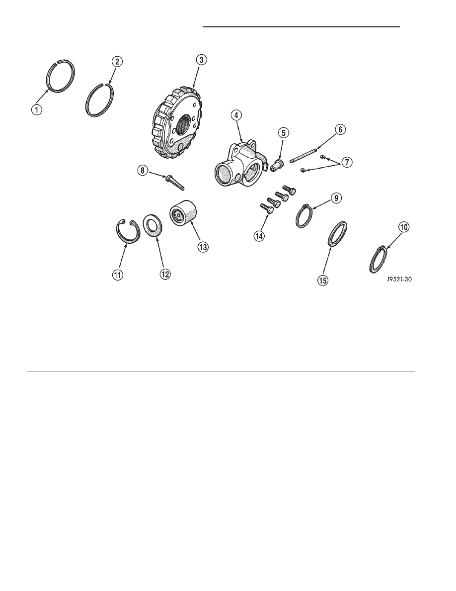
Fig. 219 Governor Components

1 – SEAL RING (PLAIN END)
2 – SEAL RING (HOOK END)
3 – PARK GEAR
4 – GOVERNOR BODY
5 – GOVERNOR VALVE
6 – VALVE SHAFT
7 – E-CLIPS (2)
8 – FILTER

9 – SNAP RING (THIN)
10 – SNAP RING (THICK)
11 – SNAP RING
12 – RETAINER WASHER
13 – GOVERNOR WEIGHT ASSEMBLY
14 – GOVERNOR BODY BOLTS (4)
15 – WASHER

21 - 192

AUTOMATIC TRANSMISSION—30RH

XJ

CLEANING AND INSPECTION (Continued)

Inspect the valves and plugs for scratches, burrs,

nicks, or scores. Also inspect the coating on the alu-
minum valves and plugs (Fig. 223). If the coating is
damaged or worn through, the valve (or valve body)
should be replaced.

Aluminum valves and plugs should not be sanded

or polished under any circumstances. However, minor
burrs or scratches on steel valves and plugs can be
removed with crocus cloth but do not round off the
valve or plug edges. Squareness of these edges is
vitally important. These edges prevent foreign matter
from lodging between the valves, plugs and bore.

Inspect all the valve and plug bores in the valve

body. Use a penlight to view the bore interiors.
Replace the valve body if any bores are distorted or
scored. Inspect all of the valve body springs. The
springs must be free of distortion, warpage or broken
coils.

Trial fit each valve and plug in its bore to check

freedom of operation. When clean and dry, the valves
and plugs should drop freely into the bores. Valve
body bores do not change dimensionally with use. If
the valve body functioned correctly when new, it will
continue to operate properly after cleaning and
inspection. It should not be necessary to replace a
valve body assembly unless it is damaged in han-
dling.

Fig. 220 Park Sprag, Shaft And Spring

1 – SPRAG SHAFT
2 – PARALLEL JAW SNAP RING PLIERS
3 – SPRAG
4 – SPRING

Fig. 221 Park Sprag Reaction Plug And Spring

Location

1 – SPRING CLIP
2 – REACTION PLUG

Fig. 222 Correct Position Of Sprag And Spring

1 – SPRAG SHAFT
2 – SPRAG LOCKING LUG
3 – SPRING

XJ

AUTOMATIC TRANSMISSION—30RH

21 - 193

CLEANING AND INSPECTION (Continued)

TRANSMISSION

Clean the case in a solvent tank. Flush the case

bores and fluid passages thoroughly with solvent.
Dry the case and all fluid passages with compressed
air. Be sure all solvent is removed from the case and
that all fluid passages are clear.

NOTE: Do not use shop towels or rags to dry the
case (or any other transmission component) unless
they are made from lint-free materials. Lint will
readily adhere to case surfaces and transmission
components and will circulate throughout the trans-
mission after assembly. A sufficient quantity of lint
can block fluid passages and interfere with valve
body operation.

Inspect the case for cracks, porous spots, worn

servo bores, or damaged threads. However, the case
will have to be replaced if it exhibits damage or wear.

Lubricate the front band adjusting screw and lock-

nut with petroleum jelly and thread it part way into
the case. Be sure the screw turns freely and does not
bind. Install the locknut on the screw after checking
screw thread operation.

Inspect all the transmission bushings during over-

haul. Bushing condition is important as worn, scored
bushings contribute to low pressures, clutch slip and
accelerated wear of other components. Replace worn,
or scored bushings, or if doubt exists about bushing
condition.

Use recommended tools to replace bushings. The

tools are sized and designed to remove, install and
seat bushings correctly. The bushing replacement

Fig. 223 Valve Body Components

1 – GOVERNOR PLUG END PLATE
2 – SHUTTLE VALVE
3 – 1–2 GOVERNOR PLUG
4 – VALVE BODY
5 – REGULATOR VALVE THROTTLE PRESSURE PLUG
6 – SLEEVE
7 – LINE PRESSURE PLUG
8 – RETAINER
9 – 1–2 SHIFT VALVE
10 – 1–2 SHIFT CONTROL VALVE

11 – KICKDOWN LIMIT VALVE
12 – END PLATE
13 – THROTTLE PRESSURE PLUG
14 – KICKDOWN LIMIT VALVE BODY
15 – E-RING
16 – 2–3 SHIFT VALVE
17 – GUIDES
18 – 2–3 GOVERNOR PLUG
19 – PRIMARY SPRING
20 – SHUTTLE VALVE THROTTLE PLUG

21 - 194

AUTOMATIC TRANSMISSION—30RH

XJ

CLEANING AND INSPECTION (Continued)

tools are included in Bushing Tool Sets C-3887-B, or
C-3887-J.

Pre-sized

service

bushings

are

available

for

replacement purposes. Only the sun gear bushings
are not serviced. Replace the gear as an assembly if
the bushings are severely scored, or worn.

Heli-Coil inserts are recommended for repairing

damaged, stripped or worn threads in aluminum
parts. Stainless steel inserts are preferred.

The use of crocus cloth is permissible where neces-

sary, providing it is used carefully. When used on
valves, use extreme care to avoid rounding off sharp
edges. Sharp edges are vital as they prevent foreign
matter from getting between the valve and valve
bore.

Do not reuse oil seals, gaskets, seal rings, or

O-rings during overhaul. Replace these parts as a
matter of course. Also do not reuse snap rings or
E-clips that are bent or distorted. Replace these parts
as well.

Lubricate transmission parts with Mopar

t ATF

Plus 3, Type 7176 transmission fluid during assem-
bly. Use Mopar

t Door Ease, or Ru-Glyde to lubricate

piston seals and O-rings. Use petroleum jelly on
thrust washers and to hold parts in place during
reassembly.

OVERRUNNING CLUTCH/LOW-REVERSE
DRUM/OVERDRIVE PISTON RETAINER

Clean the overrunning clutch assembly, clutch cam,

low-reverse drum, and overdrive piston retainer in
solvent. Dry them with compressed air after clean-
ing.

Inspect condition of each clutch part after cleaning.

Replace the overrunning clutch roller and spring
assembly if any rollers or springs are worn or dam-
aged, or if the roller cage is distorted, or damaged.
Replace the cam if worn, cracked or damaged.

Replace the low-reverse drum if the clutch race,

roller surface or inside diameter is scored, worn or
damaged. Do not remove the clutch race from
the low-reverse drum under any circumstances.
Replace the drum and race as an assembly if
either component is damaged.

Examine the overdrive piston retainer carefully for

wear, cracks, scoring or other damage. Be sure the
retainer hub is a snug fit in the case and drum.
Replace the retainer if worn or damaged.

FRONT SERVO

Clean the servo piston components with solvent

and dry them with compressed air. Wipe the band
clean with lint free shop towels.

Replace the front band if distorted, lining is

burned, flaking off, or worn to the point where the
grooves in the lining material are no longer visible.

Inspect the servo components (Fig. 224). Replace

the springs if collapsed, distorted or broken. Replace
the guide, rod and piston if cracked, bent, or worn.
Discard the servo snap ring if distorted or warped.

Check the servo piston bore for wear. If the bore is

severely scored, or damaged, it will be necessary to
replace the case.

Replace any servo component if doubt exists about

condition. Do not reuse suspect parts.

REAR SERVO

Remove and discard the servo piston seal ring (Fig.

225). Then clean the servo components with solvent
and dry with compressed air. Replace either spring if
collapsed, distorted or broken. Replace the plug and
piston if cracked, bent, or worn. Discard the servo
snap rings and use a new ones at assembly.

OIL PUMP AND REACTION SHAFT SUPPORT

(1) Clean pump and support components with sol-

vent and dry them with compressed air.

(2) Check condition of the seal rings and thrust

washer on the reaction shaft support. The seal rings
do not need to be replaced unless cracked, broken, or
severely worn.

(3) Inspect the pump and support components.

Replace the pump or support if the seal ring grooves
or machined surfaces are worn, scored, pitted, or
damaged. Replace the pump gears if pitted, worn
chipped, or damaged.

Fig. 224

1 – PISTON RINGS
2 – O-RING
3 – SNAP-RING
4 – SEAL RING
5 – PISTON ROD GUIDE
6 – SNAP-RING
7 – SERVO SPRING
8 – PISTON ROD
9 – SERVO PISTON

XJ

AUTOMATIC TRANSMISSION—30RH

21 - 195

CLEANING AND INSPECTION (Continued)


Content   ..  412  413  414  415   ..