Jeep XJ. Manual - part 352


  Index      Jeep     Jeep XJ - service repair manual 2001 year


Search            


Content   ..  350  351  352  353   ..


Jeep XJ. Manual - part 352


(4) Place the key way on the pump shaft to the 11

o’clock position as viewed from the front of pump.
Install the pump into the rear of timing gear cover
while aligning key way on pump shaft into pump
gear.

(5) Install and snug the 3 injection pump mount-

ing nuts. This is not the final tightening sequence.

(6) Remove the special gear puller and adapter

tools from timing gear cover.

(7) Install the injection pump drive gear nut.

Tighten nut to 88 N·m (65 ft. lbs.) torque.

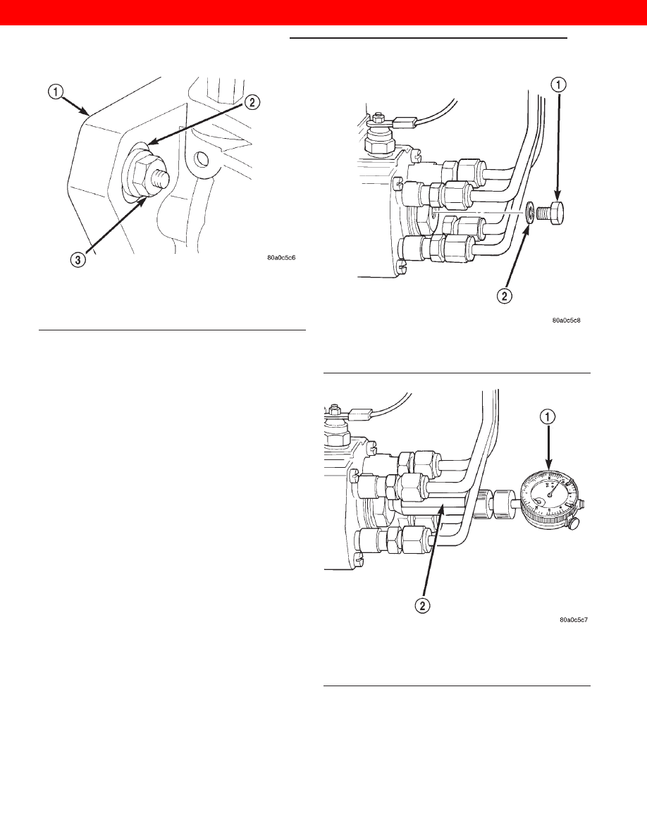
(8) Remove the access plug and plug washer at

rear of pump (Fig. 36). Thread special dial indicator
adapter tool VM.1011 (Fig. 37) into this opening.
Hand tighten only.

(9) Attach special dial indicator tool VM.1013 into

the adapter tool (Fig. 37)

(10) Using a socket attached to the front of the

crankshaft, rotate the engine in a counter-clockwise
direction until the dial gage indicator stops moving
(20–25° before TDC).

(11) Set the dial indicator to 0mm. Be sure the tip

of the dial indicator is touching the tip inside the
adapter tool.

(12) Rotate the engine clockwise until special

alignment tool VM# 1043 can be inserted through the
hole in the bottom of the clutch housing, stopping the
flywheel rotation. This position is #1Cylinder TDC
Compression. Engine must be at TDC #1 com-
pression firing stroke.

(13) The gauge reading should be at 0.55 mm

(with new gears installed specification should
be 0.59–0.60mm)
. If not, the pump must be rotated
for adjustment:

(a) Loosen the three injection pump mounting

nuts at the mounting flanges. These flanges are
equipped with slotted holes. The slotted holes are
used to rotate and position the injection pump for
fuel timing. Loosen the three nuts just enough to
rotate the pump.

Fig. 35 Injection Pump Mounting Nuts

1 – MOUNTING FLANGE
2 – SLOTTED HOLES (3)
3 – PUMP MOUNTING NUTS (3)

Fig. 36 Access Plug at Rear of Pump

1 – ACCESS PLUG
2 – WASHER

Fig. 37 Installing Dial Indicator and Special Adapter

Tools

1 – DIAL INDICATOR TOOL
2 – ADAPTER TOOL VM1011

14 - 18

FUEL SYSTEM—2.5L DIESEL ENGINE

XJ

REMOVAL AND INSTALLATION (Continued)

2000 JEEP CHEROKEE

(b) Rotate the pump until 0.55 mm is indicated

on the dial indicator gauge. If while rotating the
pump the 0.55 mm specification is passed do not
attempt to rotate the pump in the opposite direc-
tion. You must rotate the pump back below the
0.25 mm specification and start the procedure over
from the start of the TDC procedure. This will pre-
vent a false reading due to gear backlash.

(c) Tighten the three pump mounting nuts to 30

N·m (22 ft. lbs.) torque.

(d) Recheck the dial indicator after tightening

the pump mounting nuts. Gauge should still be
reading 0.55 mm.
(14) Remove dial indicator and adapter tools.
(15) Install access plug and washer to rear of

injection pump.

(16) Install plug at timing gear cover.
(17) Install and connect the four high–pressure

fuel lines to the fuel injection pump. Also connect
fuel lines at the fuel injectors. For procedures, refer
to High–Pressure Fuel Lines in this group.

(18) Install electrical connector at engine coolant

temperature sensor.

(19) Connect electrical connector at fuel shutdown

solenoid.

(20) Connect the main engine wiring harness to

the glow plugs.

(21) Connect the fuel timing solenoid pigtail har-

ness to the engine wiring harness.

(22) Connect the overflow valve/banjo fitting (fuel

return line assembly). Replace copper gaskets before
installing.

(23) Connect the rubber fuel return and supply

hoses to metal lines at pump. Tighten hose clamps to
2 N·m (20 in. lbs.) torque.

(24) Install generator assembly.
(25) Install engine accessory drive belt. Refer to

Group 7, Cooling System for procedures.

(26) Install negative battery cable to battery.
(27) Start the engine and bring to normal operat-

ing temperature.

(28) Check for fuel leaks.

FUEL INJECTORS

Four fuel injectors are used on each engine. Of

these four, two different types are used. The fuel
injector used on cylinder number one is equipped
with a fuel injector sensor (Fig. 38). The other three
fuel injectors are identical. Do not place the fuel
injector equipped with the fuel injector sensor
into any other location except the cylinder
number one position.

REMOVAL

(1) Disconnect negative battery cable at battery.

(2) Thoroughly clean the area around the injector

with compressed air.

(3) Remove the fuel drain hoses (tubes) at each

injector (Fig. 39) being serviced. Each of these hoses
is slip–fit to the fitting on injector.

Fig. 38 Fuel Injector Sensor — #1 Cylinder

1 – NEEDLE MOVEMENT SENSOR
2 – FUEL INJECTOR (NUMBER 1 CYLINDER ONLY)
3 – COPPER WASHER
4 – SENSOR CONNECTOR

Fig. 39 Fuel Injector—Typical

1 – FUEL INJECTOR
2 – LINE FITTING
3 – HIGH-PRESSURE FUEL LINE
4 – FUEL DRAIN TUBES

XJ

FUEL SYSTEM—2.5L DIESEL ENGINE

14 - 19

REMOVAL AND INSTALLATION (Continued)

2000 JEEP CHEROKEE

(4) Remove the high–pressure fuel line at injector

being removed. Refer to High–Pressure Fuel Lines in
this group for procedures.

(5) Remove the injector using special socket tool

number VM.1012A. When removing cylinder number
one injector, thread the wiring harness through the
access hole on the special socket (Fig. 40).

(6) Remove and discard the copper washer (seal) at

bottom of injector (Fig. 38).

INSTALLATION

(1) Clean the injector threads in cylinder head.
(2) Install new copper washer (seal) to injector.
(3) Install injector to engine. Tighten to 70 N·m

(52 ft. lbs.) torque.

(4) Install high–pressure fuel lines. Refer to High–

Pressure Fuel Lines in this group for procedures.

(5) Install fuel drain hoses (tubes) to each injector.

Do not use clamps at fuel drain hoses.

(6) Connect negative battery cable to battery.
(7) Bleed the air from the high–pressure lines. Refer

to the Air Bleed Procedure section of this group.

FUEL TANK

REMOVAL

(1) Disconnect negative cable from battery.
(2) Insert fuel siphon hose into fuel filler neck and

push it into the tank.

(3) Drain fuel tank dry into holding tank or a

properly labeled diesel safety container.

(4) Raise vehicle on hoist.
(5) Disconnect both the fuel fill and fuel vent rub-

ber hoses at the fuel tank.

(6) Disconnect fuel supply and return lines from

the steel supply line (Fig. 41).

The fuel reservoir module electrical connec-

tor has a retainer that locks it in place.

(7) Slide electrical connector lock to unlock.

(8) Push down on connector retainer (Fig. 43) and

pull connector off module.

Fig. 40 Wiring Harness Through Socket

1 – FUEL INJECTOR
2 – WIRING HARNESS (NUMBER 1 CYLINDER ONLY)
3 – SPECIAL SOCKET
4 – FUEL INJECTOR SENSOR (NUMBER 1 CYLINDER ONLY)

Fig. 41 Fuel Tank Connections at Front of Tank

1 – FUEL SUPPLY LINE CONNECTION
2 – FUEL PUMP MODULE CONNECTOR
3 – FRONT OF FUEL TANK
4 – EVAP CANISTER VENT LINE CONNECTION

Fig. 42 Fuel Fill/Vent Hose Index Marks

1 – FUEL TANK
2 – CLAMP INDEX MARKS
3 – TANK INDEX TANGS
4 – HOSE INDEX MARKS
5 – FUEL FILL HOSE
6 – CLAMP INDEX MARKS
7 – CLAMPS
8 – FUEL VENT HOSE

14 - 20

FUEL SYSTEM—2.5L DIESEL ENGINE

XJ

REMOVAL AND INSTALLATION (Continued)

2000 JEEP CHEROKEE

(9) Use a transmission jack to support fuel tank.

Remove bolts from fuel tank straps.

(10) Lower tank slightly. Carefully remove filler

hose from tank.

(11) Lower the fuel tank. Remove clamp and

remove fuel filler tube vent hose. Remove fuel tank
from vehicle.

INSTALLATION

(1) Position fuel tank on transmission jack. Con-

nect fuel filler tube vent hose and replace clamp.

(2) Raise tank into position and carefully work

filler tube into tank. A light coating of clean engine
oil on the tube end may be used to aid assembly.

(3) Feed filler vent line thorough frame rail. Care-

ful not to cross lines.

(4) Tighten strap bolts to 9 N·m (80 in. lbs.).

Remove transmission jack.

CAUTION: Ensure straps are not twisted or bent
before or after tightening strap nuts.

(5) Connect

module

electrical

connector.

Place

retainer in locked position.

(6) Lubricate the fuel supply and return lines with

clean 30 weight engine oil, install the quick connect
fuel fitting. Refer to Tube/Fitting Assembly in the
Fuel Delivery section of this Group.

(7) Attach filler line to filler tube. Pull on connec-

tor to make sure of connection.

(8) Fill fuel tank, replace cap, and connect battery

negative cable.

FUEL RESERVOIR MODULE

REMOVAL

WARNING:

THE FUEL RESERVOIR OF THE FUEL

MODULE DOES NOT EMPTY OUT WHEN THE TANK
IS DRAINED. THE FUEL IN THE RESERVOIR WILL
SPILL OUT WHEN THE MODULE IS REMOVED.

(1) Disconnect negative cable from battery.
(2) Drain fuel tank dry into holding tank or a

properly labeled diesel safety container.

(3) Raise vehicle on hoist.
(4) Use a transmission jack to support the fuel

tank. Remove bolts from fuel tank straps. Lower
tank slightly.

(5) Clean area around fuel reservoir module and

tank to keep dirt and foreign material out of tank.

(6) Disconnect fuel lines from fuel module by

depressing quick connect retainers with thumb and
fore finger.

(7) Slide

module

electrical

connector

lock

to

unlock.

(8) Push down on connector retainer and pull con-

nector off module.

(9) Using Special Tool 6856, remove plastic locknut

counterclockwise to release pump module (Fig. 44).

(10) Carefully remove module and o-ring from tank.
(11) Discard old o-ring.

INSTALLATION

(1) Thoroughly clean locknut threads and mating

fule tank threads. Use a soap/water solution. Do Not
use carburetor cleaner to clean threads.

(2) Apply clean water to the o-ring seal and place

on the mating fuel tank threads.

Fig. 43 Module Connector Retainer and Lock

1 – PUSH DOWN ON RETAINER
2 – CONNECTOR LOCK

Fig. 44 Fuel Reservoir Module Lock Nut Removal

1 – SPECIAL TOOL 6856
2 – LOCKNUT

XJ

FUEL SYSTEM—2.5L DIESEL ENGINE

14 - 21

REMOVAL AND INSTALLATION (Continued)

2000 JEEP CHEROKEE


Content   ..  350  351  352  353   ..