Jeep XJ. Manual - part 330


  Index      Jeep     Jeep XJ - service repair manual 2001 year


Search            


Content   ..  328  329  330  331   ..


Jeep XJ. Manual - part 330


CAUTION: Heatshield is very sharp. Wear gloves to
prevent injury.

(19) Remove the exhaust downpipe heatshield by

pulling straight up.

(20) Remove the (5) bolts attaching the exhaust

downpipe to the turbocharger and remove pipe.

(21) Remove the (8) exhaust manifold retaining

bolts, it is necessary to access the bolt behind the
manifold outlet from the underneath of the vehicle.

(22) Remove the exhaust manifold and turbo-

charger assembly from the vehicle

(23) Place assembly in a vice to remove the (3)

exhaust manifold to turbocharger retaining nuts (Fig.
8).

Cleaning

Always use new gaskets during assembly. All gas-

ket mating surfaces must be cleaned of old gasket
material to produce a smooth and dirt free sealing
surface for the new gasket.

INSTALLATION

(1) Transfer the oil return line to the new turbo-

charger (Fig. 8).

(2) Install the turbo on the exhaust manifold (Fig.

8). Torque the nuts to 32 N·m (23 ft. lbs.).

(3) Install the exhaust manifold and turbocharger

assembly in the vehicle

(4) Install the (8) exhaust manifold retaining nuts.

Torque nuts to 32 N·m (23 ft. lbs.).

(5) Install the exhaust manifold downpipe. Torque

bolts to 32 N·m (23 ft. lbs.).

CAUTION: Heatshield is very sharp. Wear gloves to
prevent injury.

(6) Slide the exhaust downpipe heatshield down

over pipe. Do not attempt to strap heatshield in posi-
tion at this time, wait until vehicle is raised on hoist.

(7) Install the oil supply line on turbocharger.

Torque bango bolt fitting to 27 N·m (20 ft. lbs.).

(8) Connect the heater hoses.
(9) Position and install the exhaust manifold heat-

shield. Torque bolts to 11 N·m (97 in. lbs.).

(10) Raise the vehicle on a hoist.
(11) Connect the turbocharger oil return line to the

engine block (Fig. 9).

(12) Strap the exhaust downpipe heatshield in its

original position.

(13) Install the exhaust system support clamp

(Fig. 10). Torque nuts to 23 N·m (17 ft. lbs.).

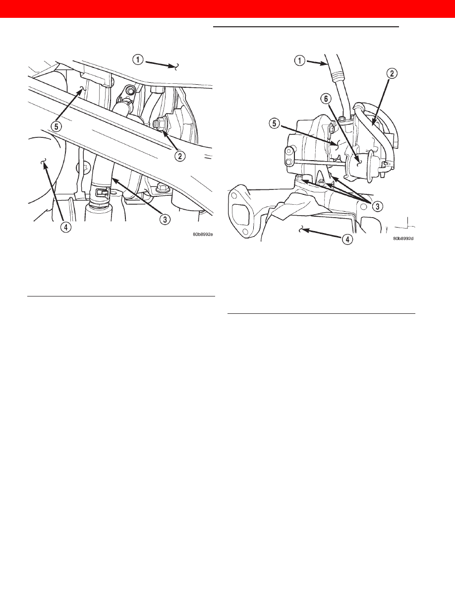
Fig. 7 Turbocharger Oil Return Hose

1 – VEHICLE UNDERBODY
2 – RIGHT ENGINE MOUNT THROUGHBOLT NUT
3 – TURBOCHARGER OIL RETURN HOSE
4 – EXHAUST MANIFOLD DOWNPIPE
5 – TURBOCHARGER

Fig. 8 Turbocharger / Exhaust Manifold Assembly

1 – OIL RETURN LINE
2 – WASTEGATE VACUUM SUPPLY HOSE
3 – TURBO TO EXHAUST MANIFOLD RETAINING NUTS
4 – BENCH VISE
5 – TURBOCHARGER ASSEMBLY (REMOVED FROM VEHICLE)
6 – WASTEGATE VACUUM ACTUATOR

11 - 4

EXHAUST SYSTEM AND TURBOCHARGER

XJ

REMOVAL AND INSTALLATION (Continued)

2000 JEEP CHEROKEE

(14) Connect the exhaust system at the (3) bolt

flange (Fig. 10). Torque the bolts to 23 N·m (17 ft.
lbs.).

(15) Lower the vehicle from the hoist.

(16) Install the intake manifold elbow and EGR

valve as an assembly. Torque bolts to 27 N·m (20 ft.
lbs.).

(17) Install the (2) bolts holding the EGR tube to

the EGR valve. Torque bolts to 27 N·m (20 ft. lbs.).

(18) Install the innercooler inlet and outlet hoses

on the engine (Fig. 11).

(19) Install the EGR vacuum supply hose on the

EGR valve.

(20) Install the air filter cover and outlet hose on

turbocharger (Fig. 11).

(21) Connect the breather hose on the air cleaner

outlet hose (Fig. 11).

(22) Fill the cooling system. Refer to Group 7,

Cooling System for procedure.

(23) Connect the negative battery cable
(24) Start the engine and check for leaks.

EXHAUST MANIFOLD AND TURBOCHARGER
(RHD)

REMOVAL

(1) Disconnect the negative battery cable
(2) Disconnect the breather hose from the air

cleaner outlet hose.

Fig. 9 Turbocharger Oil Return Hose

1 – VEHICLE UNDERBODY
2 – RIGHT ENGINE MOUNT THROUGHBOLT NUT
3 – TURBOCHARGER OIL RETURN HOSE
4 – EXHAUST MANIFOLD DOWNPIPE
5 – TURBOCHARGER

Fig. 10 Exhaust System Inlet Pipe Connection

1 – EXHAUST INLET PIPE RETAINING BOLTS
2 – EXHAUST SYSTEM SUPPORT CLAMP

Fig. 11 Engine Compartment

1 – INTAKE MANIFOLD ELBOW
2 – BREATHER HOSE
3 – INNERCOOLER OUTLET HOSE
4 – AIR FILTER COVER
5 – AIR FILTER OUTLET (FRESH AIR) HOSE
6 – INNERCOOLER INLET HOSE
7 – HEATER CORE COOLANT SUPPLY HOSES

XJ

EXHAUST SYSTEM AND TURBOCHARGER

11 - 5

REMOVAL AND INSTALLATION (Continued)

2000 JEEP CHEROKEE

(3) Remove the air filter cover and the hose from

the turbocharger, remove the assembly.

(4) Raise the vehicle on a hoist.
(5) Drain the cooling system. Refer to Group 7,

Cooling System for the procedure.

(6) Remove the exhaust system support clamp

(Fig. 12).

(7) Disconnect the exhaust system at the (3) bolt

flange (Fig. 12).

CAUTION: Heatshield is very sharp. Wear gloves to
prevent injury.

(8) Unstrap the exhaust downpipe heatshield (Fig.

13).

CAUTION: Heatshield is very sharp. Wear gloves to
prevent injury.

(9) Remove the exhaust downpipe heatshield by

pulling straight down.

(10) Disconnect the turbocharger oil return hose

from the engine block (Fig. 14).

(11) Lower the vehicle from the hoist.
(12) Disconnect the heater supply and return

hoses from the right side of the engine. Remove the
steel line support bracket from the top of the rocker
cover and position the assembly out of the way

(13) Remove the EGR vacuum supply hose from

the EGR valve.

(14) Remove the innercooler inlet and outlet hoses

from the engine.

(15) Remove the (2) bolts holding the EGR tube to

the EGR valve.

Fig. 12 Exhaust System Inlet Pipe Connection

1 – EXHAUST INLET PIPE RETAINING BOLTS
2 – EXHAUST SYSTEM SUPPORT CLAMP

Fig. 13 Exhaust Downpipe Heatshield

1 – EXHAUST MANIFOLD DOWNPIPE HEATSHIELD RETAINING

STRAPS

Fig. 14 Turbocharger Oil Return Hose

1 – VEHICLE UNDERBODY
2 – RIGHT ENGINE MOUNT THROUGHBOLT NUT
3 – TURBOCHARGER OIL RETURN HOSE
4 – EXHAUST MANIFOLD DOWNPIPE
5 – TURBOCHARGER

11 - 6

EXHAUST SYSTEM AND TURBOCHARGER

XJ

REMOVAL AND INSTALLATION (Continued)

2000 JEEP CHEROKEE

(16) Remove the intake manifold elbow and the

EGR valve as an assembly.

(17) Remove the EGR tube from the exhaust man-

ifold.

(18) Remove the (2) exhaust manifold heatshield

retaining bolts and remove the heatshield (Fig. 15).

(19) Remove the oil pressure supply line from the

turbocharger (Fig. 15).

(20) Remove the clutch master cylinder heatshield

(Fig. 15).

(21) Remove the turbocharger oil supply line from

the engine block (Fig. 16).

(22) Working inside of the vehicle, remove the

Knee Blocker. Refer to Group 8E, Instrument Panel
Systems for the procedure.

(23) Disconnect the neutral safety switch electrical

connector at the clutch pedal.

(24) Remove the (2) clutch master cylinder retain-

ing nuts from the bulkhead.

(25) Working from the inside of the engine com-

partment, remove the clutch master cylinder from
the bulkhead and position the cylinder and line
assembly out of the way.

(26) Remove the (5) bolts attaching the exhaust

downpipe to the turbocharger and remove the pipe.

(27) Remove the (8) exhaust manifold retaining

bolts, it is necessary to access the bolt behind the
manifold outlet from the underneath of the vehicle.

(28) Remove the steering shaft pinchbolt and slide

the shaft straight off of the gearbox input shaft. Posi-
tion aside.

(29) Remove the exhaust manifold and the turbo-

charger assembly from the vehicle

(30) Place the turbo assembly in a vice to remove

the (3) exhaust manifold to turbocharger retaining
nuts (Fig. 17).

Cleaning

Always use new gaskets during assembly. All gas-

ket mating surfaces must be cleaned of all old gasket
material to produce a smooth and dirt free sealing
surface for the new gasket.

INSTALLATION

(1) Install the turbocharger on the exhaust mani-

fold (Fig. 17). Torque nuts to 32 N·m (23 ft. lbs.).

(2) Install the exhaust manifold and turbocharger

assembly in the vehicle

(3) Install the (8) exhaust manifold retaining nuts,

it is necessary to access the bolt behind the manifold
outlet from underneath the vehicle. Torque nuts to 32
N·m (23 ft. lbs.).

(4) Install the exhaust manifold downpipe. Torque

the bolts to 32 N·m (23 ft. lbs.).

Fig. 15 2.5L Turbo Diesel — Heatshields

1 – CLUTCH MASTER CYLINDER HEATSHIELD
2 – TURBO OIL PRESSURE SUPPLY LINE
3 – TURBOCHARGER
4 – EXHAUST MANIFOLD HEATSHIELD RETAINING BOLTS

Fig. 16 R. H. D. Turbo Position & Orientation

1 – CLUTCH MASTER CYLINDER
2 – EXHAUST DOWNPIPE HEATSHIELD
3 – TURBOCHARGER OIL PRESSURE SUPPLY LINE AT TURBO
4 – TURBOCHARGER OIL PRESSURE SUPPLY LINE AT ENGINE

BLOCK

5 – ACTUATOR VACUUM SUPPLY
6 – TURBOCHARGER WASTEGATE ACTUATOR

XJ

EXHAUST SYSTEM AND TURBOCHARGER

11 - 7

REMOVAL AND INSTALLATION (Continued)

2000 JEEP CHEROKEE


Content   ..  328  329  330  331   ..