Jeep XJ. Manual - part 292


  Index      Jeep     Jeep XJ - service repair manual 2001 year


Search            


Content   ..  290  291  292  293   ..


Jeep XJ. Manual - part 292


INSTALLATION

(1) Inspect the engine cylinder head cover for

cracks. Replace the cover, if cracked.

NOTE: The

original

dark

grey

gasket

material

should NOT be removed. If sections of the gasket
material are missing or are compressed, replace the
engine cylinder head cover. However, sections with
minor damage such as small cracks, cuts or chips
may be repaired with a hand held applicator. The
new material must be smoothed over to maintain
gasket height. Allow the gasket material to cure
prior to engine cylinder head cover installation.

(2) If a replacement cover is installed, transfer the

CCV valve grommet the oil filler cap from the origi-
nal cover to the replacement cover.

(3) Install engine cylinder head cover. Tighten the

mounting bolts to 13 N·m (115 in. lbs.) torque.

(4) Connect the CCV hoses (Fig. 52).
(5) Connect negative cable to battery.
(6) Install the air inlet hose and resonator.

ROCKER ARMS AND PUSH RODS

This procedure can be done with the engine in or

out of the vehicle.

REMOVAL

(1) Remove the engine cylinder head cover. (Refer

to procedure in this section)

(2) Check for rocker arm bridges which are caus-

ing misalignment of the rocker arm to valve tip area.

(3) Remove the capscrews at each bridge and pivot

assembly (Fig. 53). Alternately loosen the capscrews
one turn at a time to avoid damaging the bridges.

(4) Remove the bridges, pivots and corresponding

pairs of rocker arms (Fig. 53). Place them on a bench
in the same order as removed.

(5) Remove the push rods and place them on a

bench in the same order as removed.

(6) Clean all the components with cleaning sol-

vent.

(7) Use compressed air to blow out the oil passages

in the rocker arms and push rods.

INSTALLATION

(1) Lubricate the ball ends of the push rods with

Mopar Engine Oil Supplement, or equivalent and
install push rods in their original locations. Ensure
that the bottom end of each push rod is centered in
the tappet plunger cap seat.

(2) Using Mopar Engine Oil Supplement, or equiv-

alent, lubricate the area of the rocker arm that the

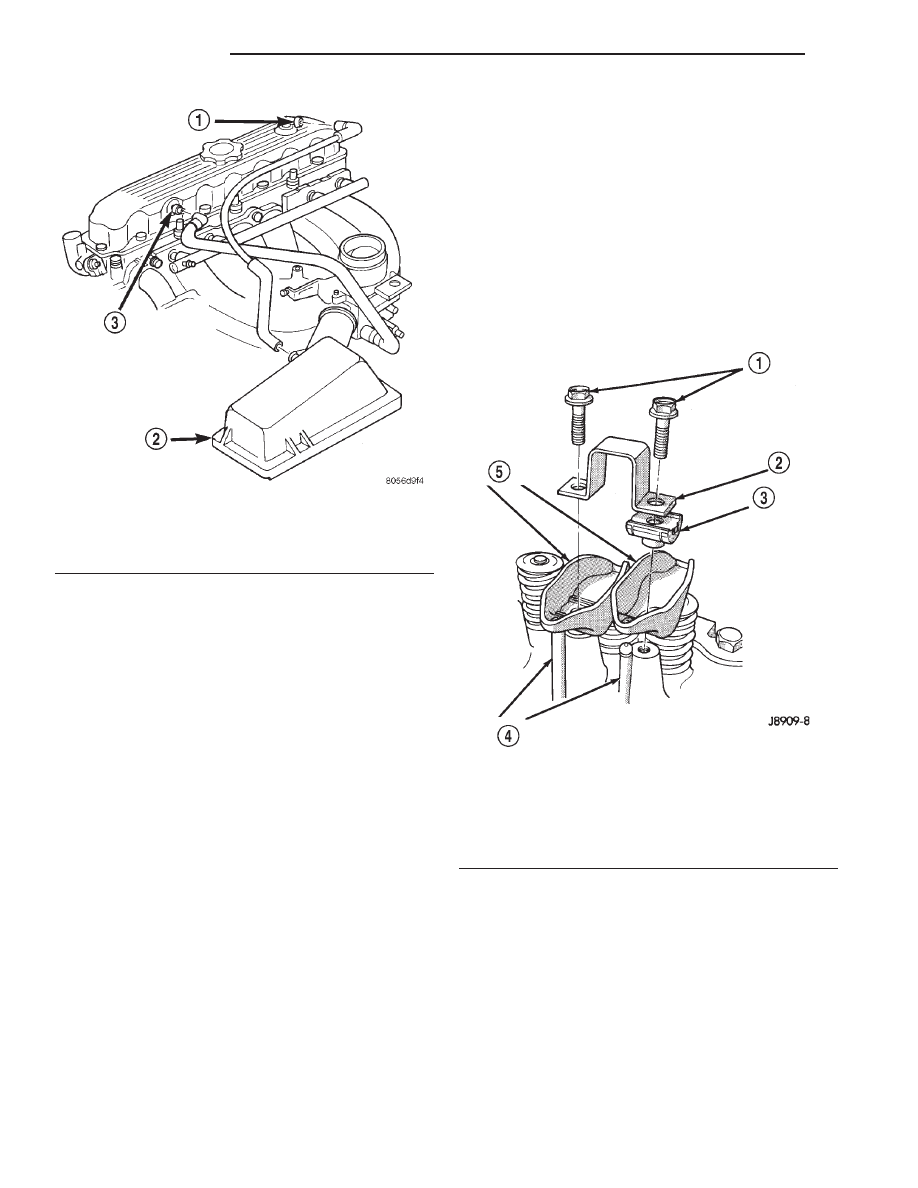
Fig. 52 Engine Cylinder Head Cover

1 – AIR INLET FITTING
2 – AIR FILTER COVER
3 – FIXED ORIFICE FITTING

Fig. 53 Rocker Arm Assembly

1 – CAPSCREWS
2 – BRIDGE
3 – PIVOT ASSEMBLY
4 – PUSH RODS
5 – ROCKER ARMS

9 - 36

2.5L ENGINE

XJ

REMOVAL AND INSTALLATION (Continued)

pivot contacts. Install rocker arms, pivots and bridge
above each cylinder in their original position.

(3) Loosely install the capscrews through each

bridge.

(4) At each bridge, tighten the capscrews alter-

nately, one turn at a time, to avoid damaging the
bridge. Tighten the capscrews to 28 N·m (21 ft. lbs.)
torque.

(5) Install the engine cylinder head cover.

VALVE SPRING AND SEAL

This procedure can be done with the engine cylin-

der head installed on the block.

REMOVAL

Each valve spring is held in place by a retainer

and a set of conical valve locks. The locks can be
removed only by compressing the valve spring.

(1) Remove the engine cylinder head cover. Refer

to procedure in this section.

(2) Remove cap screws, bridge and pivot assem-

blies and rocker arms for access to each valve spring
to be removed.

(3) Remove push rods. Retain the push rods,

bridges, pivots and rocker arms in the same
order and position as removed.

(4) Inspect the springs and retainer for cracks and

possible signs of weakening.

(5) Remove the spark plug(s) adjacent to the cylin-

der(s) below the valve springs to be removed.

(6) Install a 14 mm (1/2 inch) (thread size) air hose

adaptor in the spark plug hole.

(7) Connect an air hose to the adapter and apply

air pressure slowly. Maintain at least 621 kPa (90
psi) of air pressure in the cylinder to hold the valves
against their seats. For vehicles equipped with an air
conditioner, use a flexible air adaptor when servicing
the No.1 cylinder.

(8) Tap the retainer or tip with a rawhide hammer

to loosen the lock from the retainer. Use Valve Spring
Compressor Tool MD-998772A to compress the spring
and remove the locks (Fig. 54).

(9) Remove valve spring and retainer (Fig. 54).
(10) Remove valve stem oil seals (Fig. 54). Note

the valve seals are different for intake and exhaust
valves. The top of each seal is marked either INT
(intake/black in color) or EXH (exhaust/brown in
color). DO NOT mix the seals.

INSTALLATION

Inspect the valve stems, especially the grooves. An

Arkansas smooth stone should be used to remove
nicks and high spots.

CAUTION: Install oil seals carefully to prevent dam-
age from the sharp edges of the valve spring lock
grove.

(1) Lightly push the valve seal over the valve stem

and valve guide boss. Be sure the seal is completely
seated on the valve guide boss.

(2) Install valve spring and retainer.
(3) Compress the valve spring with Valve Spring

Compressor Tool MD-998772A and insert the valve
locks. Release the spring tension and remove the
tool. Tap the spring from side-to-side to ensure that
the spring is seated properly on the engine cylinder
head.

(4) Release air pressure and disconnect the air

hose. Remove the adaptor from the spark plug hole
and install the spark plug.

(5) Repeat the procedures for each remaining valve

spring to be removed.

(6) Install the push rods. Ensure the bottom end of

each rod is centered in the plunger cap seat of the
hydraulic valve tappet.

(7) Install the rocker arms, pivots and bridge at

their original location.

(8) Tighten the bridge cap screws alternately, one

at a time, to avoid damaging the bridge. Tighten the
cap screws to 28 N·m (21 ft. lbs.) torque.

Fig. 54 Valve and Valve Components

1 – VALVE LOCKS (3–BEAD)
2 – RETAINER
3 – VALVE STEM OIL SEAL
4 – INTAKE VALVE
5 – EXHAUST VALVE
6 – VALVE SPRING

XJ

2.5L ENGINE

9 - 37

REMOVAL AND INSTALLATION (Continued)

(9) Install the engine cylinder head cover.

CYLINDER HEAD

This procedure can be done with the engine in or

out of the vehicle.

REMOVAL

(1) Disconnect negative cable from battery.

WARNING: DO

NOT

REMOVE

THE

CYLINDER

BLOCK DRAIN PLUGS OR LOOSEN THE RADIATOR
DRAIN COCK WITH THE SYSTEM HOT AND PRES-
SURIZED BECAUSE SERIOUS BURNS FROM THE
COOLANT CAN OCCUR.

(2) Drain the coolant and disconnect the hoses at

the engine thermostat housing. DO NOT waste reus-
able coolant. If the solution is clean and is being
drained only to service the engine or cooling system,
drain the coolant into a clean container for reuse.

(3) Remove the air cleaner assembly.
(4) Remove the engine cylinder head cover. (Refer

to procedure in this section)

(5) Remove the capscrews, bridge and pivot assem-

blies and rocker arms (Fig. 55).

(6) Remove the push rods (Fig. 55). Retain the

push rods, bridges, pivots and rocker arms in
the same order as removed.

(7) Loosen the accessory drive belt at the power

steering pump bracket, if equipped or at the idler
pulley bracket (refer to Group 7, Cooling System for
the proper procedure).

(8) If equipped with air conditioning, perform the

following:

(a) Remove the bolts from the A/C compressor

mounting bracket and set the compressor aside.

(b) Remove

the

air

conditioner

compressor

bracket bolts from the engine cylinder head.

(c) Loosen the through bolt at the bottom of the

bracket.
(9) If equipped, disconnect the power steering

pump bracket. Set the pump and bracket aside. DO
NOT disconnect the hoses.

(10) Perform

fuel

pressure

release

procedure

(Refer to Group 14, fuel systems for proper proce-
dures).

(11) Remove the latch clip and disconnect the fuel

supply hose.

(12) Remove the intake and engine exhaust mani-

folds from the engine cylinder head (refer to Group
11, Exhaust System and Intake Manifold for the
proper procedures).

(13) Number and disconnect the ignition wires and

remove the spark plugs.

(14) Disconnect the coolant temperature sending

unit connector.

(15) Remove the engine cylinder head bolts.

(16) Remove the engine cylinder head and gasket

(Fig. 56).

(17) If this was the first time the bolts were

removed, put a paint dab on the top of the bolt. If the
bolts have a paint dab on the top of the bolt or it
isn’t known if they were used before, discard the
bolts.

(18) Stuff clean lint free shop towels into the cyl-

inder bores.

NOTE: If valves, springs, or seals are to be inspect-
ed/replaced at this time, refer to Valves and Valve
Springs later in this section for proper inspection
procedures.

INSTALLATION

The engine cylinder head gasket is a composition

gasket. The gasket is to be installed DRY. DO NOT
use a gasket sealing compound on the gasket.

If the engine cylinder head is to be replaced and

the original valves used, measure the valve stem
diameter. Only standard size valves can be used with
a service replacement engine cylinder head unless
the replacement head valve stem guide bores are
reamed

to

accommodate

oversize

valve

stems.

Remove all carbon buildup and reface the valves.

Fig. 55 Rocker Arm Assembly

1 – CAPSCREWS
2 – BRIDGE
3 – PIVOT ASSEMBLY
4 – PUSH RODS
5 – ROCKER ARMS

9 - 38

2.5L ENGINE

XJ

REMOVAL AND INSTALLATION (Continued)

(1) Fabricate two engine cylinder head alignment

dowels from used head bolts (Fig. 57). Use the long-
est head bolt. Cut the head of the bolt off below the
hex head. Then cut a slot in the top of the dowel to
allow easier removal with a screwdriver.

(2) Install one dowel in bolt hole No.10 and the

other dowel in bolt hole No.8 (Fig. 58).

(3) Remove the shop towels from the cylinder

bores. Coat the bores with clean engine oil.

(4) Place the engine cylinder head gasket (with the

numbers facing up) over the dowels.

(5) Place the engine cylinder head over the dowels.

CAUTION: Engine cylinder head bolts should be
reused only once. Replace the head bolts if they
were used before or if they have a paint dab on the
top of the bolt.

(6) Coat the threads of bolt No.7, only, with Loctite

PST sealant or equivalent.

(7) Install all head bolts, except No.8 and No.10.
(8) Remove the dowels.
(9) Install No.8 and No.10 head bolts.

CAUTION: During the final tightening sequence,
bolt No.7 will be tightened to a lower torque than
the rest of the bolts. DO NOT overtighten bolt No.7.

(10) Tighten the engine cylinder head bolts in

sequence according to the following procedure (Fig.
59) :

(a) Tighten all bolts in sequence (1 through 10)

to 30 N·m (22 ft. lbs.) torque.

(b) Tighten all bolts in sequence (1 through 10)

to 61 N·m (45 ft. lbs.) torque.

(c) Check all bolts to verify they are set to 61

N·m (45 ft. lbs.) torque.

(d) Tighten bolts (in sequence):

• Bolts 1 through 6 to 149 N·m (110 ft. lbs.)

torque.

• Bolt 7 to 136 N·m (100 ft. lbs.) torque.

• Bolts 8 through 10 to 149 N·m (110 ft. lbs.)

torque.

(e) Check all bolts in sequence to verify the cor-

rect torque.

(f) If not already done, clean and mark each bolt

with a dab of paint after tightening. Should you
encounter bolts which were painted in an earlier
service operation, replace them.
(11) Connect the coolant temperature sending unit

connector.

(12) Install the spark plugs and tighten to 37 N·m

(27 ft. lbs.) torque. Connect the ignition wires.

Fig. 56 Engine Cylinder Head Assembly

1 – BRIDGE
2 – PIVOT ASM.
3 – ROCKER ARM
4 – CYLINDER HEAD
5 – HEAD GASKET
6 – PUSH ROD

Fig. 57 Fabricate Alignment Dowels

1 – USED CYLINDER HEAD BOLT
2 – SLOT

Fig. 58 Alignment Dowel Locations

1 – ALIGNMENT DOWEL
2 – ALIGNMENT DOWEL

XJ

2.5L ENGINE

9 - 39

REMOVAL AND INSTALLATION (Continued)


Content   ..  290  291  292  293   ..