Jeep XJ. Manual - part 131


  Index      Jeep     Jeep XJ - service repair manual 2001 year


Search            


Content   ..  129  130  131  132   ..


Jeep XJ. Manual - part 131


clockspring latch with a small screwdriver (Fig. 15).
Gently pry both plastic latches of the clockspring
assembly to release them from the steering column
upper housing.

NOTE: If the clockspring plastic latches are broken,
be certain to remove the broken pieces from the
steering column upper housing.

(13) Remove the clockspring from the steering col-

umn. The clockspring cannot be repaired. It must be

replaced if faulty or damaged, or if the driver side
airbag has been deployed.

(14) If the removed clockspring is to be reused,

lock the clockspring rotor to the clockspring case to
maintain clockspring centering until it is reinstalled
on the steering column. This can be done by inserting
a stiff wire through the small index hole located at
about the 11 o’clock position in the centered clock-
spring rotor and case. Refer to Clockspring Center-
ing 
in the Adjustments section of this group for an
illustration of the clockspring index hole. Bend the
wire over after it has been inserted through the
index hole to prevent it from falling out.

INSTALLATION

If the clockspring is not properly centered in rela-

tion to the steering wheel, steering shaft and steer-
ing gear, it may be damaged. Refer to Clockspring
Centering 
in the Adjustments section of this group
before installing or reinstalling a clockspring.

Service replacement clocksprings are shipped pre-

centered and with a locking pin installed. This lock-
ing pin should not be removed until the clockspring
has been installed on the steering column. If the
locking pin is removed before the clockspring is
installed on a steering column, the clockspring cen-
tering procedure must be performed.

NOTE: Before starting this procedure, be certain
that the front wheels are still in the straight-ahead
position.

(1) If the removed clockspring is being reused,

remove the wire from the index hole that is locking
the clockspring rotor to the clockspring case to main-
tain clockspring centering.

(2) Be certain that the turn signal switch stalk is

in the neutral position, then carefully slide the cen-
tered clockspring down over the steering column
upper shaft until the clockspring latches engage the
steering column upper housing.

(3) If a new clockspring has been installed, remove

the locking pin that is securing the clockspring rotor
to the clockspring case and maintaining clockspring
centering.

(4) Reconnect the two instrument panel wire har-

ness connectors to the lower clockspring connector
receptacles. Be certain that the connector latches are
fully engaged.

(5) Position the steering column shrouds on the

steering column.

(6) Install and tighten the three screws that secure

the lower steering column shroud to the upper
shroud. Tighten the screws to 2 N·m (18 in. lbs.).

(7) Install the steering column opening cover onto

the instrument panel. Refer to Steering Column
Opening Cover 
in the Removal and Installation sec-

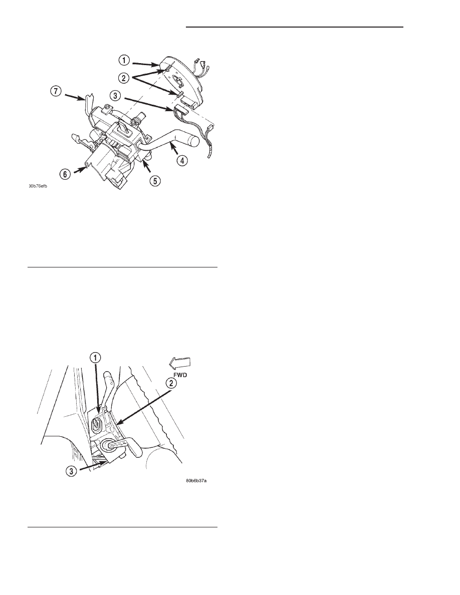
Fig. 14 Clockspring Remove/Install

1 – CLOCKSPRING
2 – LATCHES
3 – WIRE HARNESS
4 – TURN SIGNAL SWITCH LEVER
5 – WATER SHIELD BRACKET
6 – STEERING COLUMN
7 – WIPER SWITCH LEVER

Fig. 15 Upper Clockspring Latch Access Window

1 – UPPER CLOCKSPRING LATCH ACCESS WINDOW
2 – CLOCKSPRING
3 – WATER SHIELD AND BRACKET

8M - 14

PASSIVE RESTRAINT SYSTEMS

XJ

REMOVAL AND INSTALLATION (Continued)

tion of Group 8E - Instrument Panel Systems for the
procedures.

(8) Install the steering wheel onto the steering col-

umn upper shaft. Be certain to index the flats on the
hub of the steering wheel with the formations on the
inside of the clockspring rotor. Pull the upper clock-
spring wire harnesses through the lower hole in the
steering wheel armature.

(9) Install and tighten the steering wheel mount-

ing nut. Tighten the nut to 61 N·m (45 ft. lbs.). Be
certain not to pinch the wire harnesses between the
steering wheel and the nut.

(10) If the vehicle is so equipped, reconnect the

upper clockspring wire harness connector to the
steering wheel wire harness for the vehicle speed
control switches.

(11) Install the driver side airbag module onto the

steering wheel. Refer to Driver Side Airbag Mod-
ule 
in the Removal and Installation section of this
group for the procedures.

ADJUSTMENTS

CLOCKSPRING CENTERING

The clockspring is designed to wind and unwind

when the steering wheel is rotated, but is only
designed to rotate the same number of turns (about
five complete rotations) as the steering wheel can be
turned from stop to stop. Centering the clockspring
indexes the clockspring tape to other steering compo-
nents so that it can operate within its designed
travel limits. The rotor of a centered clockspring can
be rotated two and one-half turns in either direction
from the centered position, without damaging the
clockspring tape.

However, if the clockspring is removed for service

or if the steering column is disconnected from the
steering gear, the clockspring tape can change posi-
tion relative to the other steering components. The
clockspring must then be re-centered following com-
pletion of the service or the clockspring tape may be
damaged.

Service replacement clocksprings are shipped pre-

centered and with a locking pin installed. This lock-
ing pin should not be removed until the clockspring
has been installed on the steering column. If the
locking pin is removed before the clockspring is
installed on a steering column, the clockspring cen-
tering procedure must be performed.

WARNING: THE AIRBAG SYSTEM IS A SENSITIVE,
COMPLEX ELECTROMECHANICAL UNIT. BEFORE
ATTEMPTING TO DIAGNOSE OR SERVICE ANY AIR-
BAG SYSTEM OR RELATED STEERING WHEEL,
STEERING

COLUMN,

OR

INSTRUMENT

PANEL

COMPONENTS YOU MUST FIRST DISCONNECT

AND ISOLATE THE BATTERY NEGATIVE (GROUND)
CABLE. THEN WAIT TWO MINUTES FOR THE SYS-
TEM CAPACITOR TO DISCHARGE BEFORE FUR-
THER SYSTEM SERVICE. THIS IS THE ONLY SURE
WAY TO DISABLE THE AIRBAG SYSTEM. FAILURE
TO DO THIS COULD RESULT IN ACCIDENTAL AIR-
BAG DEPLOYMENT AND POSSIBLE PERSONAL
INJURY.

NOTE: Before starting this procedure, be certain to
turn the steering wheel until the front wheels are in
the straight-ahead position.

(1) Place the front wheels in the straight-ahead

position.

(2) Remove the clockspring from the steering col-

umn. Refer to Clockspring in the Removal and
Installation section of this group for the procedures.

(3) Hold the clockspring case in one hand so that it

is oriented as it would be when it is installed on the
steering column (Fig. 16).

(4) Use your other hand to rotate the clockspring

rotor clockwise to the end of its travel. Do not apply
excessive torque.

(5) From the end of the clockwise travel, rotate the

rotor about two and one-half turns counterclockwise,

Fig. 16 Clockspring

1 – LOCKING PIN
2 – ROTOR FLATS
3 – CASE
4 – UPPER CLOCKSPRING WIRE HARNESSES (WIRES NOT

SHOWN)

5 – ROTOR
6 – INDEX HOLE

XJ

PASSIVE RESTRAINT SYSTEMS

8M - 15

REMOVAL AND INSTALLATION (Continued)

until the rotor flats are horizontal. If the upper clock-
spring wire harnesses are not oriented towards the
bottom of the clockspring, rotate the rotor another
one-half turn in the counterclockwise direction.

(6) The clockspring is now centered. Lock the

clockspring rotor to the clockspring case to maintain
clockspring centering until it is reinstalled on the
steering column. This can be done by inserting a stiff
wire through the small index hole located at about
the 11 o’clock position in the centered clockspring
rotor and case. Bend the wire over after it has been
inserted through the index hole to prevent it from
falling out.

(7) The front wheels should still be in the straight-

ahead position. Install the clockspring onto the steer-
ing column. Refer to Clockspring in the Removal
and Installation section of this group for the proce-
dures.

SPECIAL TOOLS

PASSIVE RESTRAINT SYSTEMS

Puller C-3428-B

8M - 16

PASSIVE RESTRAINT SYSTEMS

XJ

ADJUSTMENTS (Continued)

ELECTRICALLY HEATED SYSTEMS

TABLE OF CONTENTS

page

page

REAR WINDOW DEFOGGER SYSTEM . . . . . . . . . . 1

HEATED SEAT SYSTEM . . . . . . . . . . . . . . . . . . . . . 8

REAR WINDOW DEFOGGER SYSTEM

TABLE OF CONTENTS

page

page

GENERAL INFORMATION

INTRODUCTION . . . . . . . . . . . . . . . . . . . . . . . . . . 1
REAR WINDOW DEFOGGER SYSTEM . . . . . . . . . 1

DESCRIPTION AND OPERATION

REAR GLASS HEATING GRID . . . . . . . . . . . . . . . . 2
OUTSIDE MIRROR HEATING GRID . . . . . . . . . . . . 2
DEFOGGER SWITCH . . . . . . . . . . . . . . . . . . . . . . 2
INSTRUMENT CLUSTER . . . . . . . . . . . . . . . . . . . . 2
DEFOGGER RELAY . . . . . . . . . . . . . . . . . . . . . . . . 3

DIAGNOSIS AND TESTING

DEFOGGER SYSTEM . . . . . . . . . . . . . . . . . . . . . . 3

REAR GLASS HEATING GRID . . . . . . . . . . . . . . . . 4
DEFOGGER SWITCH . . . . . . . . . . . . . . . . . . . . . . 4
DEFOGGER RELAY . . . . . . . . . . . . . . . . . . . . . . . . 4
INSTRUMENT CLUSTER . . . . . . . . . . . . . . . . . . . . 5

SERVICE PROCEDURES

REAR GLASS HEATING GRID REPAIR . . . . . . . . . 6

REMOVAL AND INSTALLATION

DEFOGGER SWITCH . . . . . . . . . . . . . . . . . . . . . . 6
DEFOGGER RELAY . . . . . . . . . . . . . . . . . . . . . . . . 7

GENERAL INFORMATION

INTRODUCTION

An electrically heated rear window defogger and

electrically heated outside rear view mirrors are
available factory-installed options on this model.
Refer to 8W-48 - Rear Window Defogger and 8W-62 -
Power Mirrors in Group 8W - Wiring Diagrams for
complete circuit descriptions and diagrams.

NOTE: This group covers both Left-Hand Drive
(LHD) and Right-Hand Drive (RHD) versions of this
model. Whenever required and feasible, the RHD
versions of affected vehicle components have been
constructed as mirror-image of the LHD versions.
While most of the illustrations used in this group
represent only the LHD version, the diagnostic and
service

procedures

outlined

can

generally

be

applied to either version. Exceptions to this rule
have been clearly identified as LHD or RHD, if a
special illustration or procedure is required.

REAR WINDOW DEFOGGER SYSTEM

The rear window defogger system will only operate

when the ignition switch is in the On position. When
the defogger switch is in the On position, an electric
heater grid on the rear window glass is energized.
Vehicles with the heated mirror options also have
heater grids located behind the outside rear view
mirror glass. Each of these grids produce heat to help
clear the rear window glass and outside rear view
mirrors of ice, snow, or fog.

The defogger system is controlled by a switch

installed in the instrument panel accessory switch
bezel, which is located near the bottom of the instru-
ment panel center bezel area, below the heater and
air conditioner controls. An amber indicator lamp in
the switch button will light to indicate when the
defogger system is turned on. The instrument cluster
circuitry, which contains the defogger system timer
logic, monitors the state of the defogger switch
through a hard-wired input. The instrument cluster
circuitry controls the defogger system through a
hard-wired control output to the defogger relay.

The defogger system will be automatically turned

off after a programmed time interval of about ten
minutes. After the initial time interval has expired, if

XJ

ELECTRICALLY HEATED SYSTEMS

8N - 1


Content   ..  129  130  131  132   ..