Jeep XJ. Manual - part 130


  Index      Jeep     Jeep XJ - service repair manual 2001 year


Search            


Content   ..  128  129  130  131   ..


Jeep XJ. Manual - part 130


Removal and Installation section of Group 8E -
Instrument Panel Systems for the procedures.

(8) Remove the four screws that secure the lower

flange of the passenger side airbag door to the
instrument panel upper glove box opening reinforce-
ment.

(9) Reach through and above the instrument panel

glove box opening to access and remove the two
screws that secure the passenger side airbag module
lower mounting brackets to the instrument panel
structural support.

(10) Remove the passenger side airbag module and

airbag door from the instrument panel as a unit.

(11) Remove the passenger side airbag door from

the airbag module. Refer to Passenger Side Airbag
Door 
in the Removal and Installation section of this
group for the procedures.

INSTALLATION

WARNING: USE EXTREME CARE TO PREVENT
ANY FOREIGN MATERIAL FROM ENTERING THE
PASSENGER SIDE AIRBAG MODULE, OR BECOM-
ING ENTRAPPED BETWEEN THE AIRBAG CUSHION
AND THE PASSENGER SIDE AIRBAG DOOR. FAIL-
URE TO OBSERVE THIS WARNING COULD RESULT
IN OCCUPANT INJURIES UPON AIRBAG DEPLOY-
MENT.

(1) Install the passenger side airbag door onto the

airbag module. Refer to Passenger Side Airbag
Door 
in the Removal and Installation section of this
group for the procedures.

(2) Carefully position the passenger side airbag

module and airbag door in the instrument panel as a
unit.

(3) Reach through and above the instrument panel

glove box opening to install and tighten the two
screws that secure the passenger side airbag module
lower mounting brackets to the instrument panel
structural support. Tighten the screws to 11.8 N·m
(105 in. lbs.).

(4) Install and tighten the four screws that secure

the lower flange of the passenger side airbag door to
the instrument panel upper glove box opening rein-
forcement. Tighten the screws to 2.2 N·m (20 in.
lbs.).

(5) Install the glove box into the instrument panel.

Refer to Glove Box - Roll Down in the Removal
and Installation section of Group 8E - Instrument
Panel Systems for the procedures.

(6) Install and tighten the two screws that secure

the passenger side airbag module upper mounting
brackets to the top of the instrument panel struc-
tural support. Tighten the screws to 11.8 N·m (105
in. lbs.).

(7) Install and tighten the four screws that secure

the upper flange of the passenger side airbag door to
the instrument panel structural support. Tighten the
screws to 2.2 N·m (20 in. lbs.).

(8) Engage the passenger side airbag module wire

harness connector retainer in the mounting hole on
the top of the instrument panel structural support.

(9) Reconnect the passenger side airbag module

wire harness connector to the instrument panel wire
harness. Be certain that the connector is fully
engaged and latched.

(10) Install the top cover onto the instrument

panel. Refer to Instrument Panel Top Cover in the

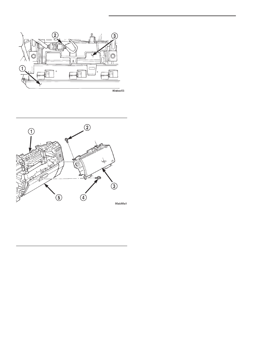
Fig. 9 Passenger Side Airbag Module Connector

1 – AIRBAG DOOR
2 – PASSENGER SIDE AIRBAG WIRE HARNESS CONNECTOR
3 – AIRBAG HOUSING

Fig. 10 Passenger Side Airbag Module Remove/

Install

1 – INSTRUMENT PANEL
2 – SCREW
3 – PASSENGER AIRBAG MODULE
4 – SCREW
5 – GLOVE BOX DOOR

8M - 10

PASSIVE RESTRAINT SYSTEMS

XJ

REMOVAL AND INSTALLATION (Continued)

Removal and Installation section of Group 8E -
Instrument Panel Systems for the procedures.

(11) Do not reconnect the battery negative cable at

this time. Refer to Airbag System in the Diagnosis
and Testing section of this group for the proper pro-
cedures.

PASSENGER SIDE AIRBAG DOOR

WARNING:

THE AIRBAG SYSTEM IS A SENSITIVE, COM-

PLEX

ELECTROMECHANICAL

UNIT.

BEFORE

ATTEMPTING TO DIAGNOSE OR SERVICE ANY AIR-
BAG SYSTEM OR RELATED STEERING WHEEL,
STEERING

COLUMN,

OR

INSTRUMENT

PANEL

COMPONENTS YOU MUST FIRST DISCONNECT
AND ISOLATE THE BATTERY NEGATIVE (GROUND)
CABLE. THEN WAIT TWO MINUTES FOR THE SYS-
TEM CAPACITOR TO DISCHARGE BEFORE FUR-
THER SYSTEM SERVICE. THIS IS THE ONLY SURE
WAY TO DISABLE THE AIRBAG SYSTEM. FAILURE
TO DO THIS COULD RESULT IN ACCIDENTAL AIR-
BAG DEPLOYMENT AND POSSIBLE PERSONAL
INJURY.

WHEN REMOVING A DEPLOYED AIRBAG MOD-

ULE, RUBBER GLOVES, EYE PROTECTION, AND A
LONG-SLEEVED SHIRT SHOULD BE WORN. THERE
MAY BE DEPOSITS ON THE AIRBAG MODULE AND
OTHER INTERIOR SURFACES. IN LARGE DOSES,
THESE DEPOSITS MAY CAUSE IRRITATION TO THE
SKIN AND EYES.

REMOVAL

(1) Disconnect and isolate the battery negative

cable. If either of the airbags has not been deployed,
wait two minutes for the system capacitor to dis-
charge before further service.

(2) Remove the passenger side airbag module from

the instrument panel. Refer to Passenger Side Air-
bag Module 
in the Removal and Installation section
of this group for the procedures.

(3) Place the passenger side airbag module on a

suitable work surface. Slide the passenger side air-
bag door sideways on the airbag module until the
keyed holes in the returns of the upper and lower
airbag door mounting flanges clear the three tabs on
the top and the bottom of the airbag module housing
(Fig. 11).

(4) Disengage the keyed holes in the returns of the

upper and lower airbag door mounting flange returns
from the three tabs on the top and the bottom of the
passenger side airbag module housing.

(5) Remove the passenger side airbag door from

the airbag module.

INSTALLATION

WARNING:

USE EXTREME CARE TO PREVENT ANY FOR-

EIGN MATERIAL FROM ENTERING THE PASSEN-
GER

SIDE

AIRBAG

MODULE,

OR

BECOMING

ENTRAPPED BETWEEN THE AIRBAG CUSHION
AND THE PASSENGER SIDE AIRBAG DOOR. FAIL-
URE TO OBSERVE THIS WARNING COULD RESULT
IN OCCUPANT INJURIES UPON AIRBAG DEPLOY-
MENT.

THE PASSENGER SIDE AIRBAG DOOR MUST

NEVER

BE

PAINTED.

REPLACEMENT

AIRBAG

DOORS ARE SERVICED IN THE ORIGINAL COL-
ORS. PAINT MAY CHANGE THE WAY IN WHICH THE
MATERIAL OF THE AIRBAG DOOR RESPONDS TO
AN AIRBAG DEPLOYMENT. FAILURE TO OBSERVE
THIS WARNING COULD RESULT IN OCCUPANT
INJURIES UPON AIRBAG DEPLOYMENT.

(1) Position the passenger side airbag door over

the airbag module.

(2) Engage the keyed holes in the returns of the

upper and lower airbag door mounting flanges with
the three tabs on the top and the bottom of the pas-
senger side airbag module housing.

(3) Slide the passenger side airbag door sideways

until the keyed holes in the returns of the upper and
lower airbag door mounting flanges are locked onto
the three tabs on the top and the bottom of the air-
bag module housing.

(4) Install the passenger side airbag module onto

the instrument panel. Refer to Passenger Side Air-
bag Module 
in the Removal and Installation section
of this group for the procedures.

Fig. 11 Passenger Side Airbag Door Remove/Install

1 – CONNECTOR
2 – AIRBAG MODULE HOUSING
3 – AIRBAG DOOR FLANGE
4 – AIRBAG DOOR
5 – TABS
6 – KEYED SLOTS

XJ

PASSIVE RESTRAINT SYSTEMS

8M - 11

REMOVAL AND INSTALLATION (Continued)

AIRBAG CONTROL MODULE

WARNING:

THE AIRBAG CONTROL MODULE CONTAINS

THE IMPACT SENSOR, WHICH ENABLES THE SYS-
TEM TO DEPLOY THE AIRBAG. BEFORE ATTEMPT-
ING TO DIAGNOSE OR SERVICE ANY AIRBAG
SYSTEM OR RELATED STEERING WHEEL, STEER-
ING COLUMN, OR INSTRUMENT PANEL COMPO-
NENTS

YOU

MUST

FIRST

DISCONNECT

AND

ISOLATE

THE

BATTERY

NEGATIVE

(GROUND)

CABLE. THEN WAIT TWO MINUTES FOR THE SYS-
TEM CAPACITOR TO DISCHARGE BEFORE FUR-
THER SYSTEM SERVICE. THIS IS THE ONLY SURE
WAY TO DISABLE THE AIRBAG SYSTEM. FAILURE
TO DO THIS COULD RESULT IN ACCIDENTAL AIR-
BAG DEPLOYMENT AND POSSIBLE PERSONAL
INJURY.

NEVER STRIKE OR KICK THE AIRBAG CON-

TROL MODULE, AS IT CAN DAMAGE THE IMPACT
SENSOR OR AFFECT ITS CALIBRATION. IF AN AIR-
BAG

CONTROL

MODULE

IS

ACCIDENTALLY

DROPPED DURING SERVICE, THE MODULE MUST
BE SCRAPPED AND REPLACED WITH A NEW UNIT.
ALWAYS REINSTALL THE AIRBAG CONTROL MOD-
ULE PROTECTIVE COVER. FAILURE TO OBSERVE
THIS WARNING COULD RESULT IN ACCIDENTAL,
INCOMPLETE, OR IMPROPER AIRBAG DEPLOY-
MENT AND POSSIBLE OCCUPANT INJURIES.

REMOVAL

(1) Disconnect and isolate the battery negative

cable. If either of the airbags has not been deployed,
wait two minutes for the system capacitor to dis-
charge before further service.

(2) Remove the center floor console from the floor

panel transmission tunnel. Refer to Full Floor Con-
sole 
in the index of this service manual for the loca-
tion of the proper center floor console removal
procedures.

(3) Remove the console rear duct from the floor

panel transmission tunnel. Refer to Ducts And Out-
lets 
in the index of this service manual for the loca-
tion

of

the

proper

console

rear

duct

removal

procedures.

(4) Remove the three screws that secure the center

floor console rear mounting bracket to the floor panel
transmission tunnel.

(5) Remove the center floor console rear mounting

bracket from the floor panel transmission tunnel.

(6) Disconnect the instrument panel wire harness

connector from the Airbag Control Module (ACM)
(Fig. 12). To disconnect the instrument panel wire
harness connector from the ACM:

(a) Squeeze

the

two

connector

latch

tabs

between the thumb and forefinger.

(b) Pull the connector straight away from the

ACM connector receptacle.

(7) Remove the three nuts that secure the ACM to

the weld studs on the ACM mounting bracket on the
floor panel transmission tunnel.

(8) Remove the ACM from the ACM mounting

bracket on the floor panel transmission tunnel.

INSTALLATION

(1) Carefully position the ACM onto the ACM

mounting bracket on the floor panel transmission
tunnel. When the ACM is correctly positioned the
arrow on the ACM label will be pointed forward in
the vehicle.

(2) Install and tighten the three nuts that secure

the ACM to the weld studs on the ACM mounting
bracket on the floor panel transmission tunnel.
Tighten the nuts to 7.3 N·m (65 in. lbs.).

(3) Reconnect the instrument panel wire harness

connector to the ACM connector receptacle. Be cer-
tain that the connector latches are fully engaged.

(4) Position the center floor console rear mounting

bracket onto the floor panel transmission tunnel over
the ACM.

(5) Install and tighten the three screws that secure

the center floor console rear mounting bracket to the
floor panel transmission tunnel. Tighten the screws
to 1.1 N·m (10 in. lbs.).

Fig. 12 Airbag Control Module Remove/Install

1 – NUT AND WASHER (3)
2 – INSTRUMENT PANEL WIRE HARNESS CONNECTOR
3 – ACM MOUNTING BRACKET
4 – SCREW (4)
5 – AIRBAG CONTROL MODULE

8M - 12

PASSIVE RESTRAINT SYSTEMS

XJ

REMOVAL AND INSTALLATION (Continued)

(6) Install the console rear duct onto the floor

panel transmission tunnel. Refer to Ducts And Out-
lets 
in the index of this service manual for the loca-
tion of the proper console rear duct installation
procedures.

(7) Install the center floor console onto the floor

panel transmission tunnel. Refer to Full Floor Con-
sole 
in the index of this service manual for the loca-
tion of the proper center floor console installation
procedures.

(8) Do not reconnect the battery negative cable at

this time. Refer to Airbag System in the Diagnosis
and Testing section of this group for the proper pro-
cedures.

CLOCKSPRING

The clockspring cannot be repaired. It must be

replaced if faulty or damaged, or if the driver side
airbag has been deployed.

WARNING: THE AIRBAG SYSTEM IS A SENSITIVE,
COMPLEX ELECTROMECHANICAL UNIT. BEFORE
ATTEMPTING TO DIAGNOSE OR SERVICE ANY AIR-
BAG SYSTEM OR RELATED STEERING WHEEL,
STEERING

COLUMN,

OR

INSTRUMENT

PANEL

COMPONENTS YOU MUST FIRST DISCONNECT
AND ISOLATE THE BATTERY NEGATIVE (GROUND)
CABLE. THEN WAIT TWO MINUTES FOR THE SYS-
TEM CAPACITOR TO DISCHARGE BEFORE FUR-
THER SYSTEM SERVICE. THIS IS THE ONLY SURE
WAY TO DISABLE THE AIRBAG SYSTEM. FAILURE
TO DO THIS COULD RESULT IN ACCIDENTAL AIR-
BAG DEPLOYMENT AND POSSIBLE PERSONAL
INJURY.

REMOVAL

NOTE: Before starting this procedure, be certain to
turn the steering wheel until the front wheels are in
the straight-ahead position.

(1) Place the front wheels in the straight-ahead

position.

(2) Remove the driver side airbag module from the

steering wheel. Refer to Driver Side Airbag Mod-
ule 
in the Removal and Installation section of this
group for the procedures.

(3) If the vehicle is so equipped, disconnect the

upper clockspring wire harness connector from the
steering wheel wire harness for the vehicle speed
control switches located within the hub cavity of the
steering wheel.

(4) Remove the nut that secures the steering wheel

armature to the steering column upper shaft, which
is located within the hub cavity of the steering wheel.

(5) Pull the steering wheel off of the steering col-

umn upper shaft spline using a steering wheel puller
(Special Tool C-3428-B).

(6) Remove the steering column opening cover

from the instrument panel. Refer to Steering Col-
umn Opening Cover 
in the Removal and Installa-
tion section of Group 8E - Instrument Panel Systems
for the procedures.

(7) If the vehicle is so equipped, move the tilt

steering column to the fully raised position.

(8) Remove the three screws that secure the lower

steering column shroud to the upper shroud (Fig. 13).

(9) If the vehicle is equipped with a standard non-

tilt steering column, loosen the two upper steering
column mounting nuts. If the vehicle is equipped
with the optional tilt steering column, move the tilt
steering column to the fully lowered position.

(10) Remove both the upper and lower shrouds

from the steering column.

(11) Disconnect the two instrument panel wire

harness connectors from the lower clockspring con-
nector receptacles (Fig. 14).

(12) The

multi-function

switch

water

shield

bracket on the top of the steering column has a small
access window which allows access to the upper

Fig. 13 Steering Column Shrouds Remove/Install

1 – UPPER SHROUD
2 – SCREW (3)
3 – LOWER SHROUD
4 – STEERING WHEEL

XJ

PASSIVE RESTRAINT SYSTEMS

8M - 13

REMOVAL AND INSTALLATION (Continued)


Content   ..  128  129  130  131   ..