Jeep XJ. Manual - part 55


  Index      Jeep     Jeep XJ - service repair manual 2001 year


Search            


Content   ..  53  54  55  56   ..


Jeep XJ. Manual - part 55


DIAGNOSIS AND TESTING

ANTILOCK BRAKES

The ABS brake system performs several self-tests

every time the ignition switch is turned on and the
vehicle is driven. The CAB monitors the systems
input and output circuits to verify the system is oper-
ating correctly. If the on board diagnostic system
senses that a circuit is malfunctioning the system
will set a trouble code in its memory.

NOTE: An audible noise may be heard during the
self-test. This noise should be considered normal.

NOTE: The MDS or DRB III scan tool is used to
diagnose the ABS system. For additional informa-
tion refer to the Antilock Brake section in Group
8W. For test procedures refer to the Chassis Diag-
nostic Manual.

SERVICE PROCEDURES

BLEEDING ABS BRAKE SYSTEM

ABS system bleeding requires conventional bleed-

ing methods plus use of the DRB scan tool. The pro-
cedure involves performing a base brake bleeding,
followed by use of the scan tool to cycle and bleed the
HCU pump and solenoids. A second base brake bleed-
ing procedure is then required to remove any air
remaining in the system.

(1) Perform base brake bleeding. Refer to base

brake section for procedure.

(2) Connect scan tool to the Data Link Connector.

(3) Select ANTILOCK BRAKES, followed by MIS-

CELLANEOUS, then ABS BRAKES. Follow the
instructions displayed. When scan tool displays TEST
COMPLETE, disconnect scan tool and proceed.

(4) Perform base brake bleeding a second time.

Refer to base brake section for procedure.

(5) Top off master cylinder fluid level and verify

proper brake operation before moving vehicle.

REMOVAL AND INSTALLATION

HYDRAULIC CONTROL UNIT/CONTROLLER
ANTILOCK BRAKES

REMOVAL

(1) Remove negative battery cable from the bat-

tery.

(2) Pull up on the CAB harness connector release

(Fig. 4) and remove connector.

(3) Remove brake lines from the HCU.
(4) Remove HCU/CAB mounting nuts and bolt

(Fig. 5) and remove HCU/CAB.

INSTALLATION

(1) Install HCU/CAB on the mounting studs.
(2) Install mounting nuts and bolt. Tighten to 11.5

N·m (102 in. lbs.).

(3) Install brake lines to the HCU and tighten to

19 N·m (170 in. lbs.).

(4) Install wiring harness connector to the CAB

and push down on the release to secure the connec-
tor.

(5) Install negative battery cable to the battery.
(6) Bleed ABS brake system.
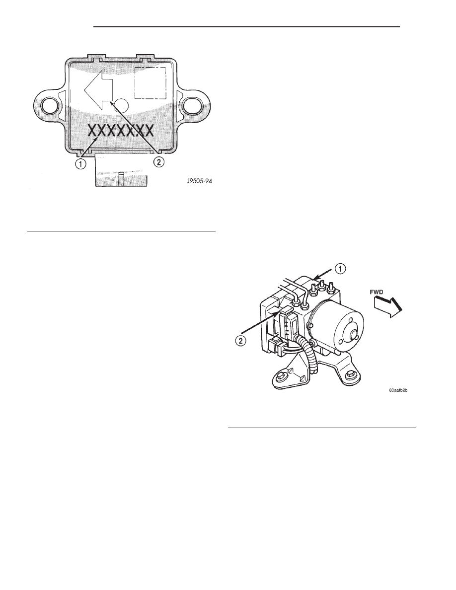
Fig. 3 G-Switch

1 – SWITCH PART NUMBER
2 – ARROW INDICATES FRONT OF SWITCH FOR PROPER

MOUNTING

Fig. 4 CAB Harness Connector Release

1 – CAB
2 – CAB HARNESS RELEASE

5 - 36

BRAKES

XJ

DESCRIPTION AND OPERATION (Continued)

FRONT WHEEL SPEED SENSOR

REMOVAL

(1) Raise vehicle and turn wheel outward for eas-

ier access to sensor.

(2) Remove sensor wire from mounting brackets.
(3) Clean sensor and surrounding area with shop

towel before removal.

(4) Remove

bolt

attaching

sensor

to

steering

knuckle and remove sensor (Fig. 6).

(5) Remove sensor wire from brackets on body and

steering knuckle.

(6) Unseat sensor wire grommet in wheel house

panel.

(7) In engine compartment, disconnect sensor wire

connector at harness plug. Then remove sensor and
wire.

INSTALLATION

(1) If original sensor will be installed, wipe all

traces of old spacer material off sensor pickup face.
Use a dry shop towel for this purpose.

(2) Apply Mopar Lock N’ Seal or Loctite

t 242 to

bolt that secures sensor in steering knuckle. Use new
sensor bolt if original bolt is worn or damaged.

(3) Position sensor on steering knuckle. Seat sen-

sor locating tab in hole in knuckle and install sensor
attaching bolt finger tight.

(4) Tighten sensor attaching bolt to 4.7 N·m (42 in.

lbs.).

(5) If original sensor has been installed, check sen-

sor air gap. Air gap should be 0.36 to 1.5 mm (0.014
to 0.059 in.). If gap is incorrect, sensor is either loose,
or damaged.

(6) Secure sensor wire to steering knuckle and

body brackets.

(7) Route sensor wire forward and behind shock

absorber. Then attach sensor wire to spring seat
bracket with grommets on sensor wire.

(8) Route sensor wire to outer sill bracket. Remove

all twists or kinks from wire.

(9) Attach sensor wire to sill bracket with grom-

met. Be sure wire is free of twists and kinks.

(10) Verify sensor wire routing. Wire should loop

forward and above sill bracket. Loose end of wire
should be below sill bracket and towards brake hose.

(11) Seat sensor wire grommet in body panel and

clip wire to brake line at grommet location.

(12) Connect sensor wire to harness in engine com-

partment.

REAR WHEEL SPEED SENSOR

REMOVAL

(1) Raise and fold rear seat forward for access to

rear sensor connectors (Fig. 7).

(2) Disconnect sensors at rear harness connectors.
(3) Push

sensor

grommets

and

sensor

wires

through floorpan.

(4) Raise vehicle.
(5) Disconnect sensor wires at rear axle connec-

tors.

(6) Remove wheel and tire assembly.

Fig. 5 HCU/CAB Mounting

1 – HCU
2 – CAB
3 – HCU/CAB BRACKET
4 – MOTOR

Fig. 6 Front Wheel Speed Sensor

1 – WHEEL SPEED SENSOR PIGTAIL
2 – STEERING KNUCKLE
3 – TONE WHEEL
4 – FRONT WHEEL SPEED SENSOR

XJ

BRAKES

5 - 37

REMOVAL AND INSTALLATION (Continued)

(7) Remove brake drum.
(8) Remove clips securing sensor wires to brake

lines, rear axle and, brake hose.

(9) Unseat sensor wire support plate grommet.
(10) Remove bolt attaching sensor to bracket and

remove sensor (Fig. 8).

INSTALLATION

(1) If original sensor is being installed, remove

any remaining pieces of cardboard spacer from sen-
sor pickup face. Use dry shop towel only to remove
old spacer material.

(2) Insert sensor wire through support plate hole.

Then seat sensor grommet in support plate.

(3) Apply Mopar Lock N’ Seal or Loctite

t 242 to

original sensor bolt. Use new bolt if original is worn
or damaged.

(4) Install sensor bolt finger tight only at this

time.

(5) If original rear sensor was installed, adjust

sensor air gap to 0.92-1.275 mm (0.036-0.05 in.). Use
feeler gauge to measure air gap (Fig. 9). Tighten sen-
sor bolt to 13 N·m (115 in. lbs.).

(6) If new sensor was installed, push cardboard

spacer on sensor face against tone ring (Fig. 10).

Then tighten sensor bolt to 13 N·m (115 in. lbs.). Cor-
rect air gap will be established as tone ring rotates
and peels spacer off sensor face.

(7) Route sensor wires to rear seat area.
(8) Feed sensor wires through floorpan access hole

and seat sensor grommets in floorpan.

(9) Verify that rear sensor wires are secured to

rear brake hose and axle with clips. Verify that wire
is clear of rotating components.

(10) Install brake drum and wheel and tire assem-

bly.

(11) Lower vehicle.
(12) Connect sensor wire to harness connector.

Then reposition carpet and fold rear seat down.

G-SWITCH

REMOVAL

(1) Raise and fold rear seat assembly forward for

access to sensor.

Fig. 7 Acceleration Switch And Rear Sensor

Connections

1 – REAR SEAT CROSSMEMBER
2 – ACCELERATION SENSOR
3 – SENSOR MOUNTING BRACKET
4 – TO R. R. WHEEL SENSOR
5 – TO L. R. WHEEL SENSOR
6 – FLOORPAN
7 – SENSOR HARNESS

Fig. 8 Rear Wheel Speed Sensor

1 – TONE WHEEL
2 – WHEEL SPEED SENSOR

Fig. 9 Setting Air Gap On Original Rear Sensor

1 – WHEEL SPEED SENSOR
2 – BRASS FEELER GAUGE
3 – TONE RING

5 - 38

BRAKES

XJ

REMOVAL AND INSTALLATION (Continued)

(2) Disconnect switch harness.
(3) Remove switch mounting screws (Fig. 11)
(4) Remove the acceleration switch.

INSTALLATION

CAUTION: The

mercury

switch

(inside

the

G-switch), will not function properly if the switch is
installed incorrectly. Verify that the switch locating
arrow is pointing to the front of the vehicle (Fig.
12).

(1) Position switch in mounting bracket.
(2) Install switch mounting bolts and tighten to 3

N·m (27.5 in. lbs.).

(3) Connect harness to switch. Be sure harness

connector is firmly seated.

(4) Move seat back to normal position.

DISASSEMBLY AND ASSEMBLY

HYDRAULIC CONTROL UNIT/CONTROLLER
ANTILOCK BRAKE

DISASSEMBLY

(1) Remove pump motor connector from the CAB.
(2) Remove CAB mounting screws from the HCU

(Fig. 13).

(3) Remove CAB from the HCU.

Fig. 10 New Rear Sensor

1 – REAR SENSOR
2 – AIR GAP SPACER ATTACHED TO SENSOR FACE

Fig. 11 G-Switch Mounting

1 – ACCELERATION SWITCH
2 – SWITCH BRACKET
3 – REAR SEAT CROSSMEMBER

Fig. 12 G-Switch

1 – SWITCH PART NUMBER
2 – ARROW INDICATES FRONT OF SWITCH FOR PROPER

MOUNTING

Fig. 13 CAB Mounting Screws

1 – MOUNTING SCREWS
2 – CAB

XJ

BRAKES

5 - 39

REMOVAL AND INSTALLATION (Continued)


Content   ..  53  54  55  56   ..