Jeep XJ. Manual - part 54


  Index      Jeep     Jeep XJ - service repair manual 2001 year


Search            


Content   ..  52  53  54  55   ..


Jeep XJ. Manual - part 54


only Mopar brake fluid or an equivalent from a
tightly sealed container.

CAUTION: Never use reclaimed brake fluid or fluid
from an container which has been left open. An
open container will absorb moisture from the air
and contaminate the fluid.

CAUTION: Never use any type of a petroleum-
based fluid in the brake hydraulic system. Use of
such type fluids will result in seal damage of the
vehicle brake hydraulic system causing a failure of
the vehicle brake system. Petroleum based fluids
would be items such as engine oil, transmission
fluid, power steering fluid, etc.

BRAKE COMPONENTS

Disc Brake Caliper

Type . . . . . . . . . . . . . . . . . . . . . . . . . . . . . Sliding

Disc Brake Rotor

Type . . . . . . . . . . . . . . . . . . . . . . . . . . Ventilated
Max. Runout . . . . . . . . . . . . . 0.12 mm (0.005 in.)
Max. Thickness Variation . . 0.013 mm (0.0005 in.)
Min. Thickness . . . . . . . . . . 22.7 mm (0.8937 in.)

Brake Drum

Size . . . . . . . . . . . . . . . . . . . . . . . . 9 in. or 10 in.

Brake Booster

Type . . . . . . . . . . . . . . . . . . . . . Dual Diaphragm

TORQUE CHART

DESCRIPTION

TORQUE

Brake Pedal

Pivot Bolt/Nut . . . . . . . . . . . . 35 N·m (26 ft. lbs.)

Brake Booster

Mounting Nuts . . . . . . . . . . . 39 N·m (29 ft. lbs.)

Master Cylinder

Mounting Nuts . . . . . . . . . 17.5 N·m (155 in. lbs.)
Brake Lines . . . . . . . . . . . . . 14 N·m (124 in. lbs.)

Combination Valve

Mounting Nuts . . . . . . . . . 17.5 N·m (155 in. lbs.)
Brake Lines . . . . . . . . . . . . . 14 N·m (124 in. lbs.)

Caliper

Mounting Bolts . . . . . . . . . . . 15 N·m (11 ft. lbs.)
Brake Hose Bolt . . . . . . . . . . . 31 N·m (23 ft. lbs.)

Wheel Cylinder

Mounting Bolts . . . . . . . . . . . . 10 N·m (7 ft. lbs.)
Brake Line . . . . . . . . . . . . . 14 N·m (124 in. lbs.)

Parking Brake

Lever Screws . . . . . . . . . 10-14 N·m (7-10 ft. lbs.)
Lever Bracket Screws . . 10-14 N·m (7-10 ft. lbs.)
Cable Retainer Nut . . . . . . . 1.5 N·m (14 in. lbs.)
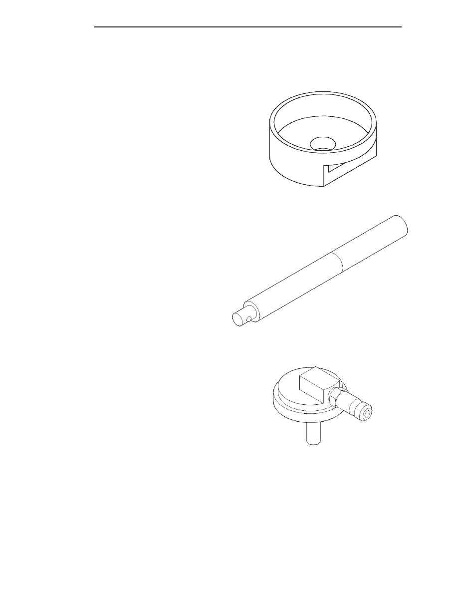
SPECIAL TOOLS

BASE BRAKES

Installer Caliper Dust Boot 8280

Handle C-4171

Adapter Pressure Bleeder 6921

5 - 32

BRAKES

XJ

SPECIFICATIONS (Continued)

ANTILOCK BRAKES

TABLE OF CONTENTS

page

page

DESCRIPTION AND OPERATION

ANTILOCK BRAKE SYSTEM . . . . . . . . . . . . . . . . 33
CONTROLLER ANTILOCK BRAKES . . . . . . . . . . . 33
HYDRAULIC CONTROL UNIT. . . . . . . . . . . . . . . . 34
WHEEL SPEED SENSORS AND TONE WHEEL . . 34
COMBINATION VALVE . . . . . . . . . . . . . . . . . . . . . 35
G-SWITCH . . . . . . . . . . . . . . . . . . . . . . . . . . . . . . 35
ABS WARNING LAMP . . . . . . . . . . . . . . . . . . . . . 35

DIAGNOSIS AND TESTING

ANTILOCK BRAKES. . . . . . . . . . . . . . . . . . . . . . . 36

SERVICE PROCEDURES

BLEEDING ABS BRAKE SYSTEM . . . . . . . . . . . . 36

REMOVAL AND INSTALLATION

HYDRAULIC CONTROL UNIT/CONTROLLER

ANTILOCK BRAKES . . . . . . . . . . . . . . . . . . . . . 36

FRONT WHEEL SPEED SENSOR . . . . . . . . . . . . 37
REAR WHEEL SPEED SENSOR . . . . . . . . . . . . . 37
G-SWITCH . . . . . . . . . . . . . . . . . . . . . . . . . . . . . . 38

DISASSEMBLY AND ASSEMBLY

HYDRAULIC CONTROL UNIT/CONTROLLER

ANTILOCK BRAKE . . . . . . . . . . . . . . . . . . . . . . 39

SPECIFICATIONS

T0RQUE CHART . . . . . . . . . . . . . . . . . . . . . . . . . 40

DESCRIPTION AND OPERATION

ANTILOCK BRAKE SYSTEM

DESCRIPTION

The purpose of the antilock system is to prevent

wheel lockup during periods of high wheel slip. Pre-
venting lockup helps maintain vehicle braking action
and steering control.

The antilock CAB activates the system whenever

sensor signals indicate periods of high wheel slip.
High wheel slip can be described as the point where
wheel rotation begins approaching 20 to 30 percent of
actual vehicle speed during braking. Periods of high
wheel slip occur when brake stops involve high pedal
pressure and rate of vehicle deceleration.

Battery voltage is supplied to the CAB ignition ter-

minal when the ignition switch is turned to Run posi-
tion. The CAB performs a system initialization
procedure at this point. Initialization consists of a
static and dynamic self check of system electrical
components.

The static check occurs after the ignition switch is

turned to Run position. The dynamic check occurs
when vehicle road speed reaches approximately 30
kph (18 mph). During the dynamic check, the CAB
briefly cycles the pump and solenoids to verify oper-
ation.

If an ABS component exhibits a fault during ini-

tialization, the CAB illuminates the amber warning
light and registers a fault code in the microprocessor
memory.

OPERATION

During normal braking, the master cylinder, power

booster and wheel brake units all function as they

would in a vehicle without ABS. The HCU compo-
nents are not activated.

During antilock braking fluid pressure is modu-

lated according to wheel speed, degree of slip and
rate of deceleration. A sensor at each wheel converts
wheel speed into electrical signals. These signals are
transmitted to the CAB for processing and determi-
nation of wheel slip and deceleration rate.

The ABS system has three fluid pressure control

channels. The front brakes are controlled separately
and the rear brakes in tandem. A speed sensor input
signal indicating a high slip condition activates the
CAB antilock program. Two solenoid valves are used
in each antilock control channel. The valves are all
located within the HCU valve body and work in pairs
to either increase, hold, or decrease apply pressure as
needed in the individual control channels. The sole-
noid valves are not static during antilock braking.
They are cycled continuously to modulate pressure.
Solenoid cycle time in antilock mode can be mea-
sured in milliseconds.

CONTROLLER ANTILOCK BRAKES

DESCRIPTION

The CAB is mounted to the HCU and operates the

ABS system (Fig. 1) separate from other vehicle elec-
trical circuits.

OPERATION

The CAB voltage source is through the ignition

switch in the RUN position. The CAB contains dual

XJ

BRAKES

5 - 33

microprocessors. A logic block in each microprocessor
receives identical sensor signals. These signals are
processed and compared simultaneously. The CAB
contains a self check program that illuminates the
ABS warning light when a system fault is detected.
Faults are stored in a diagnostic program memory
and are accessible with the DRB scan tool. ABS
faults remain in memory until cleared, or until after
the vehicle is started approximately 50 times. Stored
faults are not erased if the battery is disconnected.

HYDRAULIC CONTROL UNIT

DESCRIPTION

The HCU consists of a valve body, pump motor,

and wire harness (Fig. 1).

OPERATION

Accumulators in the valve body store extra fluid

released to the system for ABS mode operation. The
pump provides the fluid volume needed and is oper-
ated by a DC type motor. The motor is controlled by
the CAB.

The

valves

modulate

brake

pressure

during

antilock braking and are controlled by the CAB.

The HCU provides three channel pressure control

to the front and rear brakes. One channel controls
the rear wheel brakes in tandem. The two remaining
channels control the front wheel brakes individually.

During antilock braking, the solenoid valves are

opened and closed as needed. The valves are not
static. They are cycled rapidly and continuously to
modulate pressure and control wheel slip and decel-
eration.

During normal braking, the HCU solenoid valves

and pump are not activated. The master cylinder and

power booster operate the same as a vehicle without
an ABS brake system.

During antilock braking, solenoid valve pressure

modulation occurs in three stages, pressure increase,
pressure hold, and pressure decrease. The valves are
all contained in the valve body portion of the HCU.

PRESSURE DECREASE

The outlet valve is opened and the inlet valve is

closed during the pressure decrease cycle.

A pressure decrease cycle is initiated when speed

sensor signals indicate high wheel slip at one or
more wheels. At this point, the CAB closes the inlet
then opens the outlet valve, which also opens the
return circuit to the accumulators. Fluid pressure is
allowed to bleed off (decrease) as needed to prevent
wheel lock.

Once the period of high wheel slip has ended, the

CAB closes the outlet valve and begins a pressure
increase or hold cycle as needed.

PRESSURE HOLD

Both solenoid valves are closed in the pressure

hold cycle. Fluid apply pressure in the control chan-
nel is maintained at a constant rate. The CAB main-
tains the hold cycle until sensor inputs indicate a
pressure change is necessary.

PRESSURE INCREASE

The inlet valve is open and the outlet valve is

closed during the pressure increase cycle. The pres-
sure increase cycle is used to counteract unequal
wheel speeds. This cycle controls re-application of
fluid apply pressure due to changing road surfaces or
wheel speed.

WHEEL SPEED SENSORS AND TONE WHEEL

DESCRIPTION

A speed sensor is used at each wheel. The front

sensors are mounted to the steering knuckles. The
rear sensors at the outboard end of the axle.

OPERATION

The sensors convert wheel speed into a small AC

electrical signal. This signal is transmitted to the
CAB. The CAB converts the AC signal into a digital
signal for each wheel. This voltage is generated by
magnetic induction when a tone wheel passes by the
stationary magnet of the wheel speed sensor.

A gear type tone ring serves as the trigger mecha-

nism for each sensor. The tone rings are mounted at
the outboard ends of the front and rear axle shafts.

Different sensors are used at the front and rear

wheels (Fig. 2). The front/rear sensors have the same
electrical values but are not interchangeable. The

Fig. 1 Controller Antilock Brakes

1 – HCU
2 – MOTOR
3 – CAB

5 - 34

BRAKES

XJ

DESCRIPTION AND OPERATION (Continued)

sensors have a resistance between 900 and 1300
ohms.

FRONT SENSOR AIR GAP

Front sensor air gap is fixed and not adjustable.

Only rear sensor air gap is adjustable.

Although front air gap is not adjustable, it can be

checked if diagnosis indicates this is necessary. Front
air gap should be 0.36 to 1.5 mm (0.014 to 0.059 in.). If
gap is incorrect, the sensor is either loose, or damaged.

REAR SENSOR AIR GAP

A rear sensor air gap adjustment is only needed

when reinstalling an original sensor. Replacement
sensors have an air gap spacer attached to the sensor
pickup face. The spacer establishes correct air gap
when pressed against the tone ring during installa-
tion. As the tone ring rotates, it peels the spacer off
the sensor to create the required air gap. Rear sensor
air gap is 0.92-1.275 mm (0.036-0.05 in.).

Sensor air gap measurement, or adjustment proce-

dures are provided in this section. Refer to the front,
or rear sensor removal and installation procedures as
required.

COMBINATION VALVE

DESCRIPTION

The combination valve contains a pressure differ-

ential valve and switch and a rear brake proportion-
ing valve. The valve is not repairable and must be
replaced as an assembly if diagnosis indicates this is
necessary.

OPERATION

PRESSURE DIFFERENTIAL VALVE

The pressure differential switch is connected to the

brake warning light. The switch is actuated by move-
ment of the switch valve. The switch monitors fluid
pressure in the separate front/rear brake hydraulic
circuits.

A decrease or loss of fluid pressure in either

hydraulic circuit will cause the switch valve to shut-
tle to the low pressure side. Movement of the valve
pushes the switch plunger upward. This action closes
the switch internal contacts completing the electrical
circuit to the red warning light. The switch valve will
remain in an actuated position until repairs to the
brake system are made.

PROPORTIONING VALVE

The proportioning valve is used to balance front-

rear brake action at high decelerations. The valve
allows normal fluid flow during moderate braking.
The valve only controls fluid flow during high decel-
erations brake stops.

G-SWITCH

DESCRIPTION

The G-switch is located under the rear seat. The

switch has directional arrow and must be mounted
with the arrow pointing towards the front of the
vehicle.

OPERATION

The switch (Fig. 3), provides an additional vehicle

deceleration reference during 4x4 operation. The
switch is monitored by the CAB at all times. The
switch reference signal is utilized by the CAB when
all wheels are decelerating at the same speed.

ABS WARNING LAMP

DESCRIPTION

The amber ABS warning lamp is located in the

instrument cluster. The lamp illuminates at start-up
to perform a self check. The lamp goes out when the
self check program determines the system is operat-
ing normal.

OPERATION

If an ABS component exhibits a fault the CAB will

illuminate the lamp and register a trouble code in
the microprocessor. The lamp is controlled by the
CAB. The lamp is illuminated when the CAB sends a
ground signal to the ABS relay. The ABS relay then
grounds the lamp circuit and illuminates the lamp.

Fig. 2 Wheel Speed Sensors

1 – FRONT SENSOR
2 – REAR SENSOR
3 – PICKUP FACE

XJ

BRAKES

5 - 35

DESCRIPTION AND OPERATION (Continued)


Content   ..  52  53  54  55   ..