Jeep Wrangler TJ. Manual - part 591


  Index      Jeep     Jeep Wrangler TJ - service repair manual 2005 year


Search            


Content   ..  589  590  591  592   ..


Jeep Wrangler TJ. Manual - part 591


INSTALLATION

(1) From under the instrument panel, position the

blower motor resistor into the HVAC housing.

(2) From under the instrument panel, install the

lower screw that secures the blower motor resistor to
the HVAC housing. Tighten the screw to 2 N·m (17
in. lbs.).

(3) Reach through the glove box opening and

install the upper screw that secures the blower motor
resistor to the HVAC housing. Tighten the screw to 2
N·m (17 in. lbs.).

(4) Connect the wire harness connector to the

blower motor resistor and engage the connector lock.

(5) Install the glove box (Refer to 23 - BODY/IN-

STRUMENT PANEL/GLOVE BOX - INSTALLA-
TION).

(6) Reconnect the negative battery cable.

BLOWER MOTOR SWITCH

DESCRIPTION

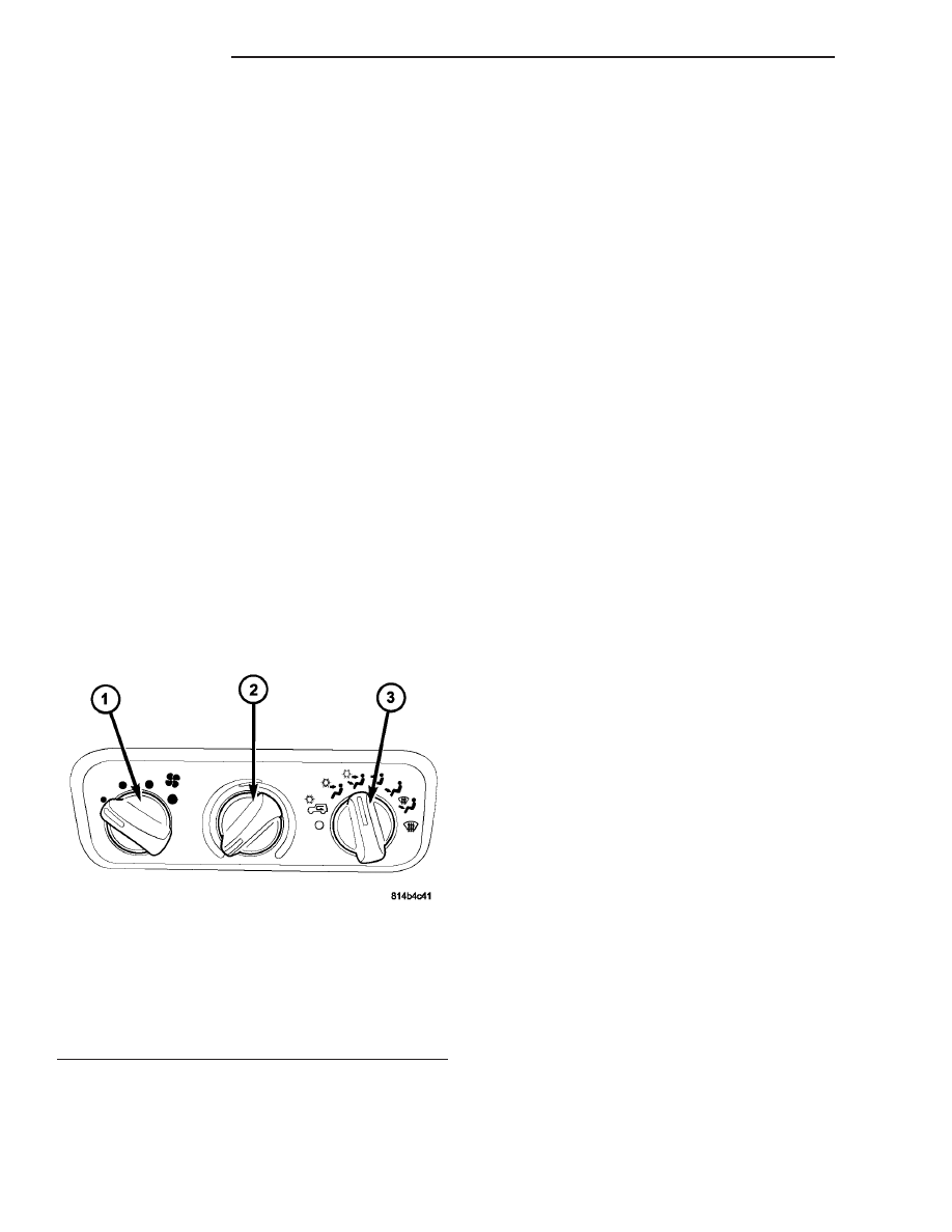
The blower motor for the heater-only or heater-A/C

system is controlled by a rotary-type blower motor
switch, mounted in the A/C-heater control (Fig. 28).
The blower motor switch allows the selection of four
different blower motor speeds and includes an Off
position.

OPERATION

The blower motor switch provides a ground path

for the blower motor through the A/C-heater mode
control. The blower motor switch directs this ground
path through or around the blower motor resistor

wires, as required to achieve the selected blower
motor speed.

The blower motor switch cannot be repaired and, if

faulty or damaged, it must be replaced. The blower
motor switch knob is available for service replace-
ment.

DIAGNOSIS AND TESTING

BLOWER MOTOR SWITCH

WARNING: On vehicles equipped with airbags, dis-
able the airbag system before attempting any steer-
ing wheel, steering column, or instrument panel
component diagnosis or service. Disconnect and
isolate the battery negative (ground) cable, then
wait two minutes for the airbag system capacitor to
discharge before performing further diagnosis or
service. This is the only sure way to disable the air-
bag system. Failure to take the proper precautions
could result in accidental airbag deployment and
possible personal injury or death.

For circuit descriptions and diagrams, refer to the

appropriate wiring information. The wiring informa-
tion includes wiring diagrams, proper wire and con-
nector repair procedures, further details on wire
harness routing and retention, as well as pin-out and
location views for the various wire harness connec-
tors, splices and grounds.

(1) Check for battery voltage at the fuse in the

power distribution center (PDC). If OK, go to Step 2.
If not OK, repair the shorted circuit or component as
required and replace the faulty fuse.

(2) Turn the ignition switch to the Off position.

Disconnect and isolate the negative battery cable.
Remove the A/C-heater control from the instrument
panel (Refer to 24 - HEATING & AIR CONDITION-
ING/CONTROLS/A/C

HEATER

CONTROL

-

REMOVAL).

Check

for

continuity

between

the

ground circuit cavity of the A/C-heater control wire
harness connector and a good ground. There should
be continuity. If OK, go to Step 3. If not OK, repair
the open circuit to ground as required.

(3) With the A/C-heater control wire harness con-

nector disconnected, place the A/C-heater mode con-
trol in any position except Off. Check for continuity
between the ground circuit terminal and each of the
blower motor driver circuit terminals of the A/C-
heater control as you move the blower motor switch
to each of the four speed positions. There should be
continuity at each driver circuit terminal in only one
blower motor switch speed position. If OK, test and
repair the blower driver circuits between the A/C-
heater control and the blower motor resistor as
required. If not OK, replace the faulty blower motor
switch.

Fig. 28 A/C-Heater Control - Typical

1 - BLOWER SPEED CONTROL
2 - TEMPERATURE SELECT COPNTROL
3 - MODE SELECT CONTROL

24 - 30

CONTROLS

TJ

BLOWER MOTOR RESISTOR (Continued)

REMOVAL

WARNING: On vehicles equipped with airbags, dis-
able the airbag system before attempting any steer-
ing wheel, steering column, or instrument panel
component diagnosis or service. Disconnect and
isolate the battery negative (ground) cable, then
wait two minutes for the airbag system capacitor to
discharge before performing further diagnosis or
service. This is the only sure way to disable the air-
bag system. Failure to take the proper precautions
could result in accidental airbag deployment and
possible personal injury or death.

(1) Disconnect and isolate the negative battery

cable.

(2) Using a trim stick C-4755 or equivalent, gently

pry the blower motor switch knob off of the switch
stem from the front of the A/C-heater control.

(3) Remove the A/C-heater control from the instru-

ment panel (Refer to 24 - HEATING & AIR CONDI-
TIONING/CONTROLS/A/C HEATER CONTROL -
REMOVAL).

(4) Remove the screw that secures the blower

motor switch to the rear of the A/C-heater control
(Fig. 29).

(5) Remove the blower motor switch from the A/C-

heater control.

INSTALLATION

(1) Position the blower motor switch onto the rear

of the A/C-heater control.

(2) Install the screw that secures the blower motor

switch to the A/C-heater control. Tighten the screw to
2 N·m (17 in. lbs.).

(3) Install the A/C-heater control (Refer to 24 -

HEATING & AIR CONDITIONING/CONTROLS/A/C
HEATER CONTROL - INSTALLATION).

(4) Install the blower motor switch knob onto the

switch stem on the front of the A/C-heater control.

(5) Reconnect the negative battery cable.

MODE DOOR ACTUATORS

DESCRIPTION

Both the heating-only system and the heating-A/C

system use two vacuum operated mode door actua-
tors to control the movement of the mode-air doors
within the HVAC housing (Fig. 30).

When vacuum is supplied by the A/C-heater control

to one side of the defrost/floor actuator or the panel
door actuator, the actuator rod is pulled into the
actuator, which moves the mode door lever and
mode-air door in one direction. When vacuum is sup-
plied by the A/C-heater control to the other side of
the actuator, the rod moves the mode-air door in the
other direction.

The mode door actuators can be accessed for ser-

vice from under the left side of the instrument panel.

The mode door actuators cannot be adjusted or

repaired and, if faulty or damaged, they must be
replaced.

Fig. 29 Blower Motor Switch

1 - A/C-HEATER CONTROL
2 - SCREW
3 - BLOWER MOTOR SWITCH
4 - VACUUM HARNESS
5 - MODE CONTROL SWITCH

Fig. 30 Vacuum Operated Mode Door Actuator -

Typical

1 - MODE DOOR ACTUATOR
2 - MOUNTING PROVISION
3 - VACUUM LINE CONNECTORS

TJ

CONTROLS

24 - 31

BLOWER MOTOR SWITCH (Continued)

REMOVAL

WARNING: On vehicles equipped with airbags, dis-
able the airbag system before attempting any steer-
ing wheel, steering column, or instrument panel
component diagnosis or service. Disconnect and
isolate the battery negative (ground) cable, then
wait two minutes for the airbag system capacitor to
discharge before performing further diagnosis or
service. This is the only sure way to disable the air-
bag system. Failure to take the proper precautions
could result in accidental airbag deployment and
possible personal injury or death.

FLOOR/DEFROST DOOR ACTUATOR

(1) Disconnect and isolate the negative battery

cable.

(2) Remove the knee blocker from the instrument

panel (Refer to 23 - BODY/INSTRUMENT PANEL/
KNEE BLOCKER - REMOVAL).

(3) Disconnect the vacuum harness from the floor/

defrost door actuator (Fig. 31).

(4) Remove the push-nut that secures the actuator

rod to the floor/defrost door lever.

(5) Using a small flat bladed tool, gently pry the

actuator latch while pulling firmly outwards on the
floor/defrost door actuator. Rotate and tilt the actua-
tor as required to remove the actuator from the
HVAC housing mount.

(6) Disengage the actuator rod from the floor/de-

frost door lever and remove the actuator.

PANEL DOOR ACTUATOR

(1) Remove the airbag control module (Refer to 8 -

ELECTRICAL/RESTRAINTS/AIRBAG

CONTROL

MODULE - REMOVAL).

(2) Remove the floor distribution duct (Refer to 24

- HEATING & AIR CONDITIONING/DISTRIBU-
TION/FLOOR DISTRIBUTION DUCT - REMOVAL).

(3) Disconnect the vacuum harness from the panel

door actuator (Fig. 32).

(4) Using a small flat bladed tool, gently pry the

actuator latch while pulling firmly outwards on the
panel door actuator. Rotate and tilt the actuator as
required to remove the actuator from the HVAC
housing mount.

(5) Using needle nose pliers, disengage the actua-

tor rod from the push-pin type retainer located on
the panel door lever and remove the actuator.

INSTALLATION

FLOOR/DEFROST DOOR ACTUATOR

(1) Rotate and tilt the floor/defrost door actuator

as required to install the actuator mount onto the
HVAC housing mounting boss. Push the actuator

onto the mount until it snaps into the locked posi-
tion.

(2) Engage the actuator rod to the floor/defrost

door lever and install the push-nut.

Fig. 31 Floor/Defrost Door Actuator

1 - VACUUM HARNESS
2 - HVAC HOUSING
3 - PUSH-NUT
4 - FLOOR/DEFROST DOOR LEVER
5 - ACTUATOR LATCH
6 - FLOOR/DEFROST (MODE) DOOR ACTUATOR

Fig. 32 Panel Door Actuator

1 - VACUUM HARNESS
2 - HVAC HOUSING
3 - ACTUATOR LATCH
4 - PANEL DOOR LEVER
5 - ACTUATOR ROD
6 - PANEL (MODE) DOOR ACTUATOR

24 - 32

CONTROLS

TJ

MODE DOOR ACTUATORS (Continued)

(3) Connect the vacuum harness to the floor/de-

frost door actuator.

(4) Install the knee blocker onto the instrument

panel (Refer to 23 - BODY/INSTRUMENT PANEL/
KNEE BLOCKER - INSTALLATION).

(5) Reconnect the negative battery cable.

PANEL DOOR ACTUATOR

(1) Using needle nose pliers, engage the actuator

rod to the push-pin type retainer located on the panel
door lever.

(2) Rotate and tilt the panel door actuator as

required to install the actuator mount onto the
HVAC housing mounting boss. Push the actuator
onto the mount until it snaps into the locked posi-
tion.

(3) Connect the vacuum harness to the panel door

actuator.

(4) Install the floor distribution duct (Refer to 24 -

HEATING & AIR CONDITIONING/DISTRIBUTION/
FLOOR DISTRIBUTION DUCT - INSTALLATION).

(5) Install the airbag control module (Refer to 8 -

ELECTRICAL/RESTRAINTS/AIRBAG

CONTROL

MODULE - INSTALLATION).

RECIRCULATION DOOR
ACTUATOR

DESCRIPTION

When equipped with A/C, a vacuum operated recir-

culation door actuator is used to control the move-
ment of the recirculation-air door within the HVAC
housing (Fig. 33).

When vacuum is supplied by the A/C-heater control

to the recirculation door actuator, the actuator link-
age is pulled into the actuator, which moves the
recirculation door lever and recirculation door to two
Recirculation position. The recirculation door actua-
tor is spring loaded, so when vacuum is released
from the actuator, the linkage moves the recircula-
tion-air door back to its static position (fresh air).

The recirculation door actuator can be accessed for

service through the glove box opening in the instru-
ment panel.

The recirculation door actuator cannot be adjusted

or repaired and, if faulty or damaged, it must be
replaced.

REMOVAL

WARNING: On vehicles equipped with airbags, dis-
able the airbag system before attempting any steer-
ing wheel, steering column, or instrument panel
component diagnosis or service. Disconnect and
isolate the battery negative (ground) cable, then
wait two minutes for the airbag system capacitor to
discharge before performing further diagnosis or
service. This is the only sure way to disable the air-
bag system. Failure to take the proper precautions
could result in accidental airbag deployment and
possible personal injury or death.

NOTE: The recirculation-air door and actuator are
used only on models equipped with A/C.

Fig. 33 Recirculation Door Actuator

1 - RECIRCULATION DOOR ACTUATOR
2 - VACUUM CONNECTOR RECEPTACLE
3 - ACTUATOR ROD
4 - ACTUATOR MOUNT

TJ

CONTROLS

24 - 33

MODE DOOR ACTUATORS (Continued)


Content   ..  589  590  591  592   ..