Jeep Wrangler TJ. Manual - part 590


  Index      Jeep     Jeep Wrangler TJ - service repair manual 2005 year


Search            


Content   ..  588  589  590  591   ..


Jeep Wrangler TJ. Manual - part 590


(3) Connect the wire harness connector to the A/C

pressure transducer.

(4) Reconnect the negative battery cable.

BLEND DOOR ACTUATOR

DESCRIPTION

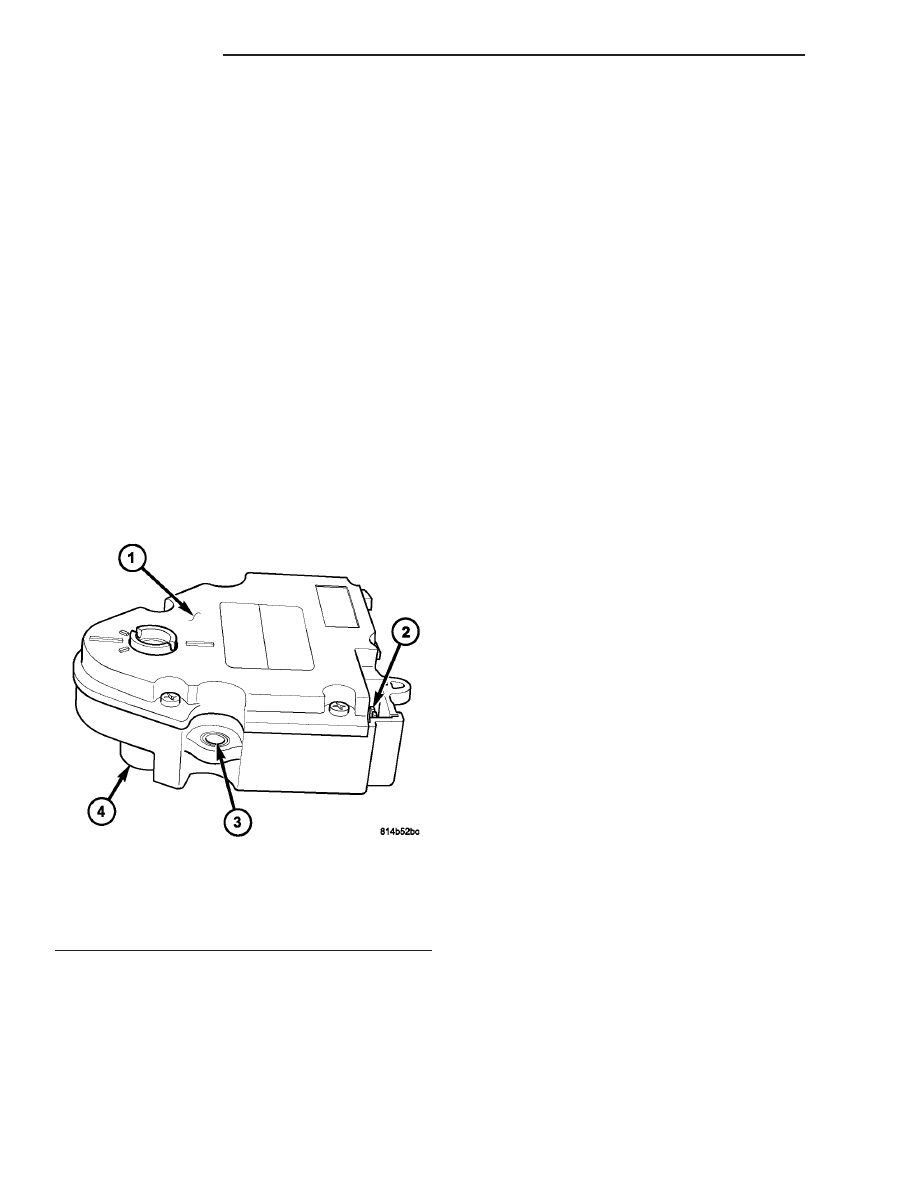
The blend door actuator is a reversible, 12-volt

direct current (DC), servo motor which mechanically
positions the blend-air door (Fig. 22). The blend door
actuator is located on the bottom of the HVAC hous-
ing.

The blend door actuator is contained within a

black molded plastic housing with an integral wire
connector receptacle. The actuator also has an output
shaft that connects it to the mode door linkage and
three integral mounting tabs that allow it to be
secured to the HVAC housing. The blend door actua-
tor requires mechanical indexing to the blend door
linkage.

The blend door actuator can be accessed for service

from under the instrument panel.

OPERATION

The blend door actuator is connected to the A/C-

heater control through the vehicle electrical system
by a dedicated three-wire lead and connector of the
HVAC wire harness. The blend door actuator can
move the blend-air door in two directions. A potenti-
ometer within the actuator allows the A/C-heater
control to know the exact position of the blend-air
door at all times.

The blend door actuator can be diagnosed using a

DRBIII

t scan tool. Refer to Body Diagnostic Proce-

dures for more information.

The blend door actuator cannot be adjusted or

repaired and, if faulty or damaged, it must be
replaced.

REMOVAL

WARNING: On vehicles equipped with airbags, dis-
able the airbag system before attempting any steer-
ing wheel, steering column, or instrument panel
component diagnosis or service. Disconnect and
isolate the negative battery (ground) cable, then
wait two minutes for the airbag system capacitor to
discharge before performing further diagnosis or
service. This is the only sure way to disable the air-
bag system. Failure to take the proper precautions
could result in accidental airbag deployment and
possible personal injury or death.

NOTE: Prior to performing this procedure, turn the
ignition key to the On position and set the A/C-
heater control in the mid-temperature position and
wait 10 seconds.

(1) Disconnect and isolate the negative battery

cable.

(2) Disconnect the wire harness connector from the

blend door actuator located at the bottom of the
HVAC housing (Fig. 23).

(3) Remove the three screws that secure the blend

door actuator to the HVAC housing and remove the
actuator.

Fig. 22 Blend Door Actuator

1 - BLEND DOOR ACTUATOR
2 - WIRE CONNECTOR RECEPTACLE
3 - MOUNTING TAB (3)
4 - ACTUATOR OUTPUT SHAFT

24 - 26

CONTROLS

TJ

A/C PRESSURE TRANSDUCER (Continued)

INSTALLATION

(1) Position the blend door actuator onto the bot-

tom of the HVAC housing. If necessary, rotate the
actuator slightly to align the actuator output shaft
with the blend door linkage.

(2) Install the three screws that secure the blend

door actuator to the HVAC housing. Tighten the
screws to 2 N·m (17 in. lbs.).

(3) Connect the HVAC wire harness connector to

the blend door actuator.

(4) Reconnect the battery negative cable.

BLOWER MOTOR RELAY

DESCRIPTION

The blower motor relay (Fig. 24) is a International

Standards Organization (ISO)-type relay. Relays con-
forming to the ISO specifications have common phys-
ical

dimensions,

current

capacities,

terminal

functions and patterns. The blower motor relay is a
electromechanical device that switches battery cur-
rent from a fuse in the power distribution center
(PDC) directly to the blower motor. The blower motor
relay is energized when the relay coil is provided a
voltage signal by the ignition switch.

The blower motor relay is mounted to the HVAC

housing, directly behind the glove box.

OPERATION

The ISO-standard blower motor relay is an electro-

mechanical switch that uses a low current input from

the ignition switch to control the high current output
to the blower motor. The movable, common feed relay
contact is held against the fixed, normally closed
relay contact by spring pressure. When the electro-
magnetic relay coil is energized, it draws the mov-
able common feed relay contact away from the fixed,
normally closed relay contact and, holds it against
the fixed, normally open relay contact. This action
allows high current to flow to the blower motor.

When the relay coil is de-energized, spring pres-

sure returns the movable relay contact back against
the fixed, normally closed contact point. The resistor
or diode is connected in parallel with the relay coil,
and helps to dissipate voltage spikes and electromag-
netic interference that can be generated as the elec-
tromagnetic field of the relay coil collapses.

The blower motor relay terminals are connected to

the vehicle electrical system through a connector
receptacle mounted to the HVAC housing. The inputs
and outputs of the blower motor relay include:

• The common feed terminal (4) receives battery

current from a fuse in the PDC at all times.

• The coil ground terminal (2) is connected to

ground at all times.

• The coil battery terminal (5) receives battery

current from a fuse in the fuse block through a fused
ignition switch output (run) circuit only when the
ignition switch is in the On position.

• The normally open terminal (1) provides battery

current to the blower motor through the blower
motor relay only when the blower motor relay coil is
energized.

• The normally closed terminal (87A) is not con-

nected to any circuit in this application, but provides

Fig. 23 Blend Door Actuator

1 - WIRE HARNESS CONNECTOR
2 - BLEND DOOR ACTUATOR
3 - SCREWS (3)
4 - HVAC HOUSING

Fig. 24 Blower Motor Relay

30 - COMMON FEED
85 - COIL GROUND
86 - COIL BATTERY
87 - NORMALLY OPEN
87A - NORMALLY CLOSED

TJ

CONTROLS

24 - 27

BLEND DOOR ACTUATOR (Continued)

a battery current output only when the blower motor
relay coil is de-energized.

The blower motor relay cannot be repaired and, if

faulty or damaged, it must be replaced. Refer to the
appropriate wiring information for diagnosis and
testing of the ISO-standard relay and for complete
HVAC wiring diagrams.

REMOVAL

WARNING: On vehicles equipped with airbags, dis-
able the airbag system before attempting any steer-
ing wheel, steering column, or instrument panel
component diagnosis or service. Disconnect and
isolate the battery negative (ground) cable, then
wait two minutes for the airbag system capacitor to
discharge before performing further diagnosis or
service. This is the only sure way to disable the air-
bag system. Failure to take the proper precautions
could result in accidental airbag deployment and
possible personal injury or death.

(1) Disconnect and isolate the negative battery

cable.

(2) Remove the glove box from the instrument

panel (Refer to 23 - BODY/INSTRUMENT PANEL/
GLOVE BOX - REMOVAL).

(3) Locate the blower motor relay through the

instrument panel glove box opening. The relay is
mounted upright and to the right of the instrument
panel harness (Fig. 25).

(4) Remove the blower motor relay from its wire

harness connector.

INSTALLATION

(1) Align the blower motor relay terminals with

the terminal cavities in the wire harness connector.

(2) Push down firmly on the blower motor relay

until the terminals are fully seated in the connector
receptacles.

(3) Install the glove box (Refer to 23 - BODY/IN-

STRUMENT PANEL/GLOVE BOX - INSTALLA-
TION).

(4) Reconnect the negative battery cable.

BLOWER MOTOR RESISTOR

DESCRIPTION

The blower motor resistor (Fig. 26) is mounted to

the rear of the HVAC housing, near the glove box.
The blower motor resistor consists of a molded plas-
tic mounting plate with an integral wire connector
receptacle. Concealed behind the mounting plate is
the resistor circuit board.

The blower motor resistor can be accessed for ser-

vice from under the instrument panel.

OPERATION

The blower motor resistor is connected to the vehi-

cle electrical system through a dedicated wire lead
and connector of the HVAC wire harness. The blower
motor resistor has multiple resistor circuits, each of
which will reduce the current flow through the
blower motor to change the blower motor speed.

The blower motor switch in the MTC heating-A/C

system directs the ground path for the blower motor

Fig. 25 Blower Motor Relay - LHD shown, RHD

similar

1 - AIR INTAKE
2 - RECIRCULATION DOOR LINKAGE
3 - RECIRCULATION DOOR ACTUATOR
4 - BLOWER MOTOR RELAY
5 - HVAC ELECTRICAL CONNECTOR
6 - HVAC VACUUM CONNECTOR
7 - HVAC HOUSING

Fig. 26 Blower Motor Resistor

1 - MOUNTING PLATE
2 - WIRE HARNESS CONNECTOR
3 - RESISTOR CIRCUIT BOARD

24 - 28

CONTROLS

TJ

BLOWER MOTOR RELAY (Continued)

through the correct resistor circuit to obtain the
selected speed. With the blower motor control in the
lowest speed position, the ground path for the blower
motor is applied through all of the resistor circuits.
Each higher speed selected with the blower motor
control

applies

the

blower

motor

ground

path

through fewer of the resistor circuits, increasing the
blower motor speed. When the blower motor control
is in the highest speed position, the blower motor
resistor is bypassed and the blower motor receives a
direct path to ground.

The blower motor resistor cannot be adjusted or

repaired and, if faulty or damaged, it must be
replaced.

DIAGNOSIS AND TESTING

BLOWER MOTOR RESISTOR

WARNING: On vehicles equipped with airbags, dis-
able the airbag system before attempting any steer-
ing wheel, steering column, or instrument panel
component diagnosis or service. Disconnect and
isolate the negative battery (ground) cable, then
wait two minutes for the airbag system capacitor to
discharge before performing further diagnosis or
service. This is the only sure way to disable the air-
bag system. Failure to take the proper precautions
could result in accidental airbag deployment and
possible personal injury or death.

NOTE: For circuit descriptions and diagrams, refer
to the appropriate wiring information. The wiring
information includes wiring diagrams, proper wire
and connector repair procedures, further details on
wire harness routing and retention, as well as pin-
out and location views for the various wire harness
connectors, splices and grounds.

(1) Disconnect and isolate the negative battery

cable.

(2) Disconnect the wire harness connector from the

blower motor resistor (Refer to 24 - HEATING & AIR
CONDITIONING/CONTROLS/BLOWER

MOTOR

RESISTOR - REMOVAL).

(3) Using

an

ohmmeter,

check

for

continuity

between all of the blower motor resistor terminals. In
each case there should be continuity. If OK, repair
the wire harness circuits between the blower motor
switch and the blower motor resistor or blower motor
as required. If not OK, replace the faulty blower
motor resistor.

REMOVAL

WARNING: On vehicles equipped with airbags, dis-
able the airbag system before attempting any steer-

ing wheel, steering column, or instrument panel
component diagnosis or service. Disconnect and
isolate the negative battery (ground) cable, then
wait two minutes for the airbag system capacitor to
discharge before performing further diagnosis or
service. This is the only sure way to disable the air-
bag system. Failure to take the proper precautions
could result in accidental airbag deployment and
possible personal injury or death.

WARNING: The blower motor resistor may get very
hot during normal operation. If the blower motor
was turned on prior to servicing the blower motor
resistor, wait five minutes to allow the blower motor
resistors to cool before performing diagnosis or
service. Failure to take this precaution can result in
possible personal injury.

(1) Disconnect and isolate the negative battery

cable.

(2) Remove the glove box (Refer to 23 - BODY/IN-

STRUMENT PANEL/GLOVE BOX - REMOVAL).

(3) Unlock the blower motor resistor wire harness

connector and disconnect the connector from the
blower motor resistor (Fig. 27).

(4) Reach through the glove box opening and

remove the upper screw that secures the blower
motor resistor to the HVAC housing.

(5) From under the instrument panel, remove the

lower screw that secures the blower motor resistor to
the HVAC housing and remove the resistor.

Fig. 27 Blower Motor Resistor-R and I

1 - WIRE HARNESS CONNECTOR
2 - BLOWER MOTOR RESISTOR
3 - SCREW (2)
4 - HVAC HOUSING

TJ

CONTROLS

24 - 29

BLOWER MOTOR RESISTOR (Continued)


Content   ..  588  589  590  591   ..