Jeep Wrangler TJ. Manual - part 513


  Index      Jeep     Jeep Wrangler TJ - service repair manual 2005 year


Search            


Content   ..  511  512  513  514   ..


Jeep Wrangler TJ. Manual - part 513


IMPELLER

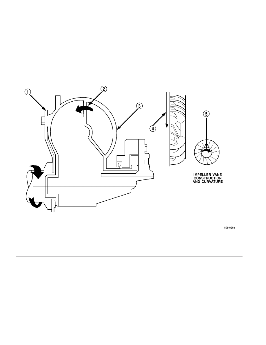
The impeller (Fig. 244) is an integral part of the

converter housing. The impeller consists of curved
blades placed radially along the inside of the housing
on the transmission side of the converter. As the con-
verter housing is rotated by the engine, so is the
impeller, because they are one and the same and are
the driving members of the system.

Fig. 244 Impeller

1 - ENGINE FLEXPLATE

4 - ENGINE ROTATION

2 - OIL FLOW FROM IMPELLER SECTION INTO TURBINE
SECTION

5 - ENGINE ROTATION

3 - IMPELLER VANES AND COVER ARE INTEGRAL

21 - 142

AUTOMATIC TRANSMISSION - 42RLE

TJ

TORQUE CONVERTER (Continued)

TURBINE

The turbine (Fig. 245) is the output, or driven,

member of the converter. The turbine is mounted
within the housing opposite the impeller, but is not
attached to the housing. The input shaft is inserted
through the center of the impeller and splined into
the turbine. The design of the turbine is similar to
the impeller, except the blades of the turbine are
curved in the opposite direction.

Fig. 245 Turbine

1 - TURBINE VANE

4 - PORTION OF TORQUE CONVERTER COVER

2 - ENGINE ROTATION

5 - ENGINE ROTATION

3 - INPUT SHAFT

6 - OIL FLOW WITHIN TURBINE SECTION

TJ

AUTOMATIC TRANSMISSION - 42RLE

21 - 143

TORQUE CONVERTER (Continued)

STATOR

The stator assembly (Fig. 246) is mounted on a sta-

tionary shaft which is an integral part of the oil
pump. The stator (1) is located between the impeller
(2) and the turbine (4) within the torque converter
case.

The stator contains an over-running clutch (1-4)

(Fig. 247), which allows the stator to rotate only in a
clockwise direction. When the stator is locked against
the over-running clutch, the torque multiplication
feature of the torque converter is operational.

TORQUE CONVERTER CLUTCH (TCC)

The TCC (Fig. 248) was installed to improve the effi-

ciency of the torque converter that is lost to the slippage
of the fluid coupling. Although the fluid coupling pro-
vides smooth, shock-free power transfer, it is natural for
all fluid couplings to slip. If the impeller (3) and turbine
(5) were mechanically locked together, a zero slippage
condition could be obtained. A hydraulic piston (6) with
friction material (7) was added to the turbine assembly
(5) to provide this mechanical lock-up.

In order to reduce heat build-up in the transmission

and buffer the powertrain against torsional vibrations,
the TCM can duty cycle the L/R-CC Solenoid to achieve
a smooth application of the torque converter clutch.
This function, referred to as Electronically Modulated
Converter Clutch (EMCC) can occur at various times
depending on the following variables:

• Shift lever position

• Current gear range

• Transmission fluid temperature

• Engine coolant temperature

• Input speed

• Throttle angle

• Engine speed

Fig. 246 Stator Location

1 - STATOR
2 - IMPELLER
3 - FLUID FLOW
4 - TURBINE

Fig. 247 Stator Components

1 - CAM (OUTER RACE)
2 - ROLLER
3 - SPRING
4 - INNER RACE

Fig. 248 Torque Converter Clutch (TCC)

1 - IMPELLER FRONT COVER
2 - THRUST WASHER ASSEMBLY
3 - IMPELLER
4 - STATOR
5 - TURBINE
6 - PISTON
7 - FRICTION DISC

21 - 144

AUTOMATIC TRANSMISSION - 42RLE

TJ

TORQUE CONVERTER (Continued)

OPERATION

The converter impeller (Fig. 249) (driving member),

which is integral to the converter housing and bolted
to the engine drive plate, rotates at engine speed.
The converter turbine (driven member), which reacts
from fluid pressure generated by the impeller, rotates
and turns the transmission input shaft.

TURBINE

As the fluid that was put into motion by the impel-

ler blades strikes the blades of the turbine, some of
the energy and rotational force is transferred into the
turbine and the input shaft. This causes both of them
(turbine and input shaft) to rotate in a clockwise
direction following the impeller. As the fluid is leav-
ing the trailing edges of the turbine’s blades it con-
tinues in a “hindering” direction back toward the
impeller. If the fluid is not redirected before it strikes
the impeller, it will strike the impeller in such a
direction that it would tend to slow it down.

STATOR

Torque multiplication is achieved by locking the

stator’s over-running clutch to its shaft (Fig. 250).
Under stall conditions (the turbine is stationary), the
oil leaving the turbine blades strikes the face of the
stator blades and tries to rotate them in a counter-
clockwise direction. When this happens the overrun-
ning clutch of the stator locks and holds the stator

from rotating. With the stator locked, the oil strikes
the stator blades and is redirected into a “helping”
direction before it enters the impeller. This circula-
tion of oil from impeller to turbine, turbine to stator,
and stator to impeller, can produce a maximum
torque multiplication of about 2.4:1. As the turbine
begins to match the speed of the impeller, the fluid
that was hitting the stator in such as way as to
cause it to lock-up is no longer doing so. In this con-
dition of operation, the stator begins to free wheel
and the converter acts as a fluid coupling.

TORQUE CONVERTER CLUTCH (TCC)

The

torque

converter

clutch

is

hydraulically

applied and is released when fluid is vented from the
hydraulic circuit by the torque converter control
(TCC) solenoid on the valve body. The torque con-
verter clutch is controlled by the Powertrain Control
Module (PCM). The torque converter clutch engages
in fourth gear, and in third gear under various con-
ditions, such as when the O/D switch is OFF, when
the vehicle is cruising on a level surface after the
vehicle has warmed up. The torque converter clutch
will disengage momentarily when an increase in
engine load is sensed by the PCM, such as when the
vehicle begins to go uphill or the throttle pressure is
increased.

Fig. 249 Torque Converter Fluid Operation

1 - APPLY PRESSURE

3 - RELEASE PRESSURE

2 - THE PISTON MOVES SLIGHTLY FORWARD

4 - THE PISTON MOVES SLIGHTLY REARWARD

TJ

AUTOMATIC TRANSMISSION - 42RLE

21 - 145

TORQUE CONVERTER (Continued)


Content   ..  511  512  513  514   ..