Jeep Wrangler TJ. Manual - part 512
The most common practice is to increase the num-
ber of turns by using thin wire that can completely
fill the available space within the solenoid housing.
The strength of the spring and the length of the
plunger also contribute to the response speed possi-
ble by a particular solenoid design.
A solenoid can also be described by the method by
which it is controlled. Some of the possibilities
include variable force, pulse-width modulated, con-
stant ON, or duty cycle. The variable force and pulse-
width modulated versions utilize similar methods to
control the current flow through the solenoid to posi-
tion the solenoid plunger at a desired position some-
where between full ON and full OFF. The constant
ON and duty cycled versions control the voltage
across the solenoid to allow either full flow or no flow
through the solenoid’s valve.
OPERATION
When an electrical current is applied to the sole-
noid coil, a magnetic field is created which produces
an attraction to the plunger, causing the plunger to
move and work against the spring pressure and the
load applied by the fluid the valve is controlling. The
plunger is normally directly attached to the valve
which it is to operate. When the current is removed
from the coil, the attraction is removed and the
plunger will return to its original position due to
spring pressure.
The plunger is made of a conductive material and
accomplishes this movement by providing a path for
the magnetic field to flow. By keeping the air gap
between the plunger and the coil to the minimum
necessary to allow free movement of the plunger, the
magnetic field is maximized.
SOLENOID/PRESSURE
SWITCH ASSY
DESCRIPTION
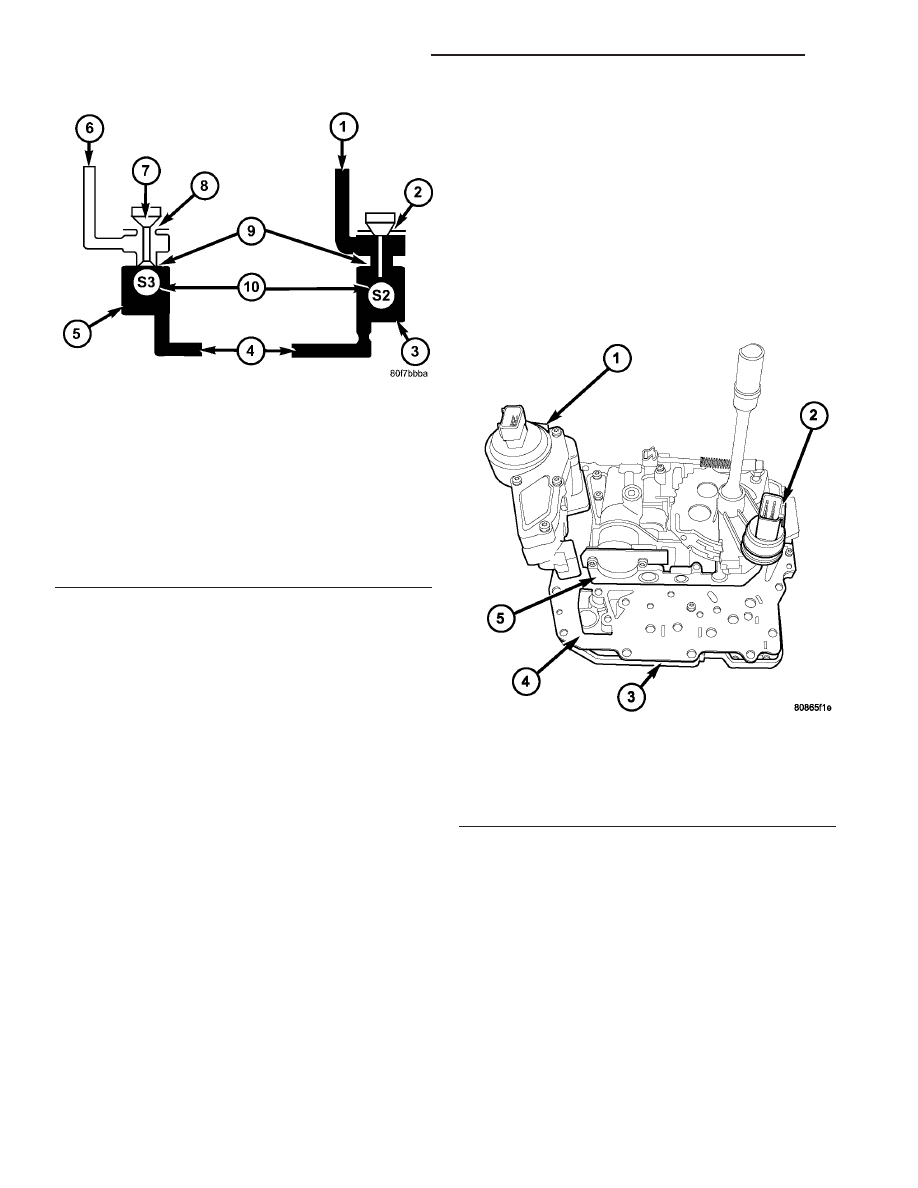
The Solenoid/Pressure Switch Assembly (1) (Fig.
238) is inside the transmission and mounted to the
valve body assembly. The assembly consists of four
solenoids that control hydraulic pressure to the L/R,
2/4, OD, and UD friction elements (transmission
clutches), and the torque converter clutch. The
reverse clutch is controlled by line pressure from the
manual valve in the valve body. The solenoids are
contained
within
the
Solenoid/Pressure
Switch
Assembly, and can only be serviced by replacing the
assembly.
The solenoid assembly also contains pressure
switches that monitor and send hydraulic circuit
information to the TCM. Likewise, the pressure
switches can only be service by replacing the assem-
bly.
Fig. 237 Low Reverse/Converter Clutch and
Overdrive Solenoids
1 - OVERDRIVE CLUTCH
2 - NO VENT
3 - OVERDRIVE SOLENOID ENERGIZED
4 - MANUAL VALVE
5 - LOW REVERSE/CONVERTER CLUTCH SOLENOID DE-
ENERGIZED
6 - SOLENOID SWITCH VALVE
7 - TAPER
8 - VENT TO SUMP
9 - ORIFICE
10 - CHECK BALL
Fig. 238 Valve Body Assembly
1 - SOLENOID/PRESSURE SWITCH ASSEMBLY
2 - TRS
3 - TRANSFER PLATE
4 - SEPARATOR PLATE
5 - VALVE BODY
21 - 138
AUTOMATIC TRANSMISSION - 42RLE
TJ
SOLENOID (Continued)