Jeep Wrangler TJ. Manual - part 224


  Index      Jeep     Jeep Wrangler TJ - service repair manual 2005 year


Search            


Content   ..  222  223  224  225   ..


Jeep Wrangler TJ. Manual - part 224


(4) Remove axle shafts.
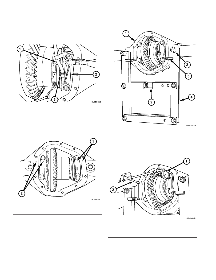
(5) Remove pressure hose from actuator assembly

(Fig. 47).

(6) Note the reference letters stamped on the bear-

ing caps and housing machined sealing surface (Fig.
48).

(7) Loosen differential bearing cap bolts.
(8) Position Spreader W-129-B with Adapter Kit

6987B on differential locating holes (Fig. 49). Install
hold-down clamps and tighten the turnbuckle finger-
tight.

(9) Install a Pilot Stud C-3288-B at the left side of

the differential housing. Attach Dial Indicator C-3339
to pilot stud (Fig. 50). Load indicator plunger against
the opposite side of the housing and zero the indica-
tor.

CAUTION: Never spread the housing over 0.38 mm
(0.015 in). Failure to heed caution may result in
damage.

Fig. 47 PRESSURE HOSE

1 - PRESSURE HOSE
2 - BEARING CAP
3 - PRESSURE HOSE CLAMP

Fig. 48 BEARING CAP REFERENCE MARKS

1 - REFERENCE MARKS
2 - REFERENCE MARKS

Fig. 49 SPREADER LOCATION

1 - DIFFERENTIAL CASE
2 - ADAPTER
3 - HOLD DOWN
4 - SPREADER
5 - TURNBUCKLE

Fig. 50 DIAL INDICATOR LOCATION

1 - DIAL INDICATOR
2 - PILOT STUD

TJ

FRONT AXLE - 216FBI

3 - 73

DIFFERENTIAL - TRU-LOK (Continued)

(10) Spread housing while measuring the distance

with the dial indicator (Fig. 51).

(11) Remove dial indicator.
(12) Remove differential bearing cap bolts and ring

gear side bearing cap.

(13) Remove differential from housing with pinion

gear side bearing cap (Fig. 52) and tag differential
bearing cups and preload shims to indicate location.

CAUTION: Do not bend actuator mounting tabs,
during differential removal. Failure to heed caution
may result in damage.

(14) Remove spreader from housing.
(15) Remove indicator switch (Fig. 53) from differ-

ential housing.

(16) Clean the housing cavity with flushing oil,

light engine oil or lint free cloth.

NOTE: Do not use water, steam, kerosene or gaso-
line for cleaning.

Fig. 51 SPREAD DIFFERENTIAL CASE

1 - DIAL INDICATOR
2 - SPREADER

Fig. 52 DIFFERENTIAL

1 - DIFFERENTIAL
2 - BEARING CAP

Fig. 53 LOCKER INDICATOR SWITCH

1 - DIFFERENTIAL CASE
2 - SWITCH

3 - 74

FRONT AXLE - 216FBI

TJ

DIFFERENTIAL - TRU-LOK (Continued)

DISASSEMBLY

(1) Install Plug C-293-3 into the differential axle

shaft hole.

(2) Remove differential case bearings with Puller

6444, Puller Rods 6444-3 and Puller Flange 6444-1.
Position puller (Fig. 54) on the differential.

(3) Position Puller Jaws 6444-7 (Fig. 55) around

the case bearing and puller flange.

(4) Position Puller Collar 6444-8 (Fig. 56) around

the puller jaws.

Fig. 55 PULLER AND JAWS

1 - PULLER
2 - ROD
3 - PLUG
4 - JAW

Fig. 56 PULLER AND COLLAR

1 - PULLER
2 - ROD
3 - PLUG
4 - COLLAR

Fig. 54 PULLER AND FLANGE

1 - PULLER
2 - ROD
3 - PLUG
4 - FLANGE

TJ

FRONT AXLE - 216FBI

3 - 75

DIFFERENTIAL - TRU-LOK (Continued)

(5) Tighten the puller nut and remove differential

case bearing.

(6) Remove actuator (Fig. 57).

ASSEMBLY

(1) Verify pressure plate tabs (Fig. 58) are seated

on the dog clutch slots.

(2) Place actuator on the pressure plate and case

bearing on the case (Fig. 59).

(3) Install differential case bearings with Installer

D-156 and Handle C-4171.

INSTALLATION

NOTE: If replacement differential bearings or differ-
ential case are being installed, differential side
bearing shim requirements may change. Refer
Adjustments (Differential Bearing Preload and Gear
Backlash) to determine the proper shim selection.

(1) Install indicator switch into the housing.
(2) Position Spreader W-129-B and adapters from

Adapter set 6987, with the tool dowel pins seated in
the locating holes (Fig. 60). Install hold-down clamps
and tighten the tool turnbuckle finger-tight.

(3) Install Pilot Stud C-3288-B at the left side of

the differential housing. Attach Dial Indicator C-3339
to pilot stud. Load indicator plunger against the
opposite side of the housing and zero indicator.

(4) Spread housing while measuring the distance

with the dial indicator.

CAUTION: Never spread over 0.38 mm (0.015 in).
Failure to heed caution may result in damage.

(5) Remove dial indicator.
(6) Install differential case with pinion gear side

bearing cap and differential preload shims in the

Fig. 57 LOCKING ACTUATOR

1 - ACTUATOR
2 - PRESSURE PLATE

Fig. 58 PRESSURE PLATE

1 - PLATE
2 - PLATE TABS

Fig. 59 ACTUATOR AND CASE BEARING

1 - CASE BEARING
2 - ACTUATOR

3 - 76

FRONT AXLE - 216FBI

TJ

DIFFERENTIAL - TRU-LOK (Continued)


Content   ..  222  223  224  225   ..